Supercharge Your Innovation With Domain-Expert AI Agents!

Grille shutter device

a shutter device and shutter technology, applied in the direction of vehicle components, component optimization, propulsion parts, etc., can solve the problems that the shutter device as described above may not be able to normally open and close the movable fins

Active Publication Date: 2021-08-05
TOYOTA JIDOSHA KK +1
View PDF0 Cites 0 Cited by
  • Summary
  • Abstract
  • Description
  • Claims
  • Application Information

AI Technical Summary

Benefits of technology

The invention is a grille shutter device used in vehicles to control the airflow and prevent damage to the engine. It includes a driving fin and a driven fin that rotate between an open and closed position. The device uses a power transmission member to transmit power from the driving fin to the driven fin. The invention is able to detect abnormalities in the power transmission path between the actuator and the movable fins, ensuring the device operates properly. This is achieved by using a first stopper that comes into contact with the power transmission member, allowing for the detection of abnormalities during the rotation of the driving fin and power transmission member. Overall, this invention improves the reliability and efficiency of grille shutter devices in vehicle engineering.

Problems solved by technology

The grille shutter device as described above may become unable to normally open and close the movable fins if a foreign object gets caught between the upper movable fin and the lower movable fin or a load acts on the link mechanism.

Method used


Image

  • Grille shutter device
  • Grille shutter device
  • Grille shutter device

Examples


first embodiment

[0029]A vehicle equipped with a grille shutter device according to a first embodiment will be described below with reference to the drawings. In the following description, an axis extending in a width direction of the vehicle will be referred to as an X-axis; an axis extending in a front-rear direction of the vehicle will be referred to as a Y-axis; and an axis extending in an up-down direction of the vehicle will be referred to as a Z-axis.

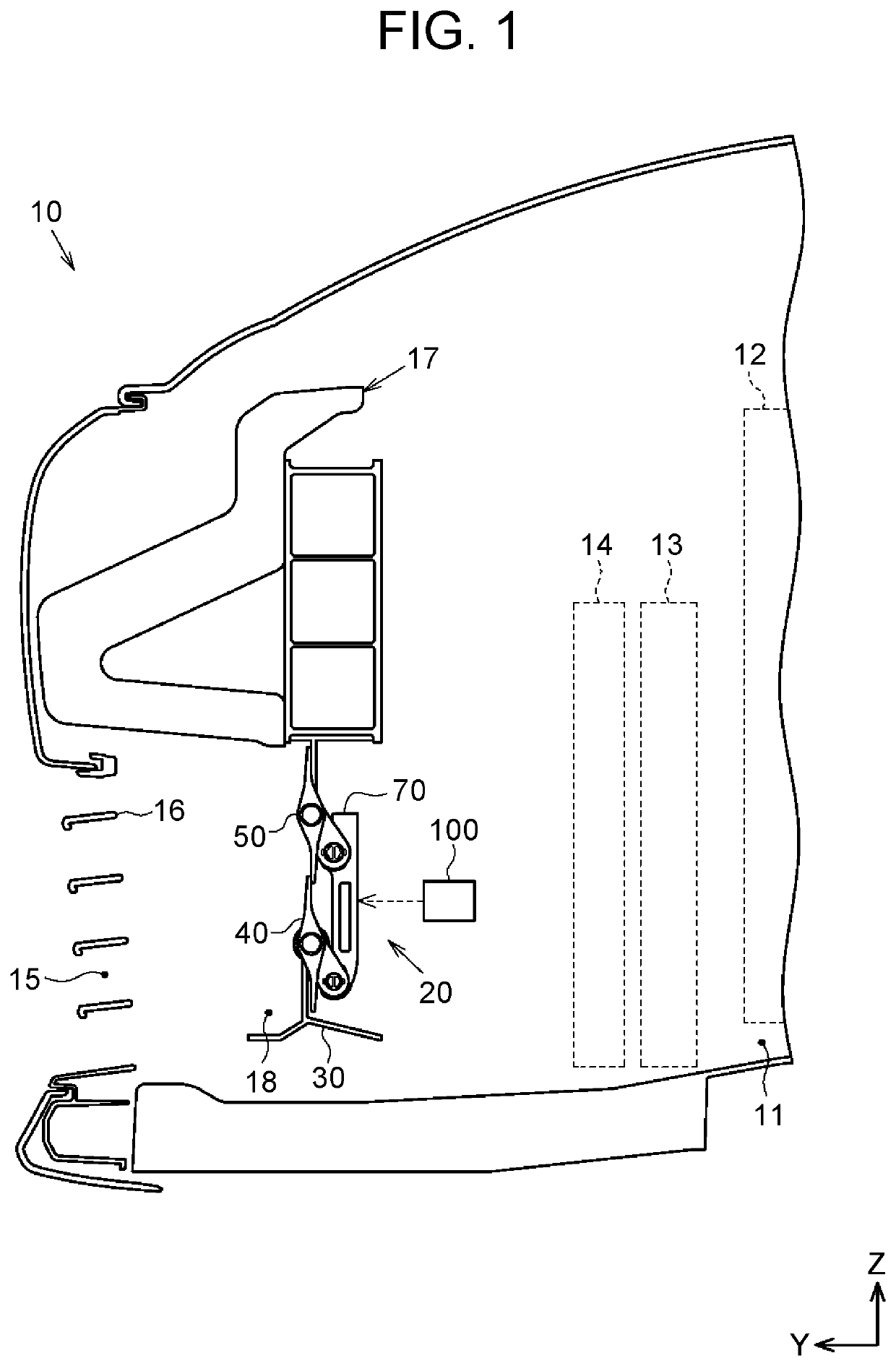
[0030]As shown in FIG. 1, a vehicle 10 includes an engine 12 that is disposed in an engine compartment 11, a radiator 13 that cools the engine 12, a fan14 that guides air to the radiator 13, and a front grille 16 that has an opening 15. The vehicle 10 further includes a bumper 17 that constitutes a front part of the vehicle 10 together with the front grille 16, and a grille shutter device 20 that adjusts a flow volume of air introduced into the engine compartment 11.

[0031]The grille shutter device 20 is disposed in an introduction passage 18 thro...

second embodiment

[0073]A grille shutter device 20A according to a second embodiment will be described below with reference to the drawings. Those components in the second embodiment that are substantially the same as in the first embodiment will be denoted by the same reference signs and description thereof will be omitted.

[0074]As shown in FIG. 11 to FIG. 13, the grille shutter device 20A includes a frame 30A that constitutes a framework of the grille shutter device 20A, a driving fin 40A and a plurality of driven fins 110, 120, 130 as one example of the “movable fins” that open and close an introduction passage 18, and an actuator 60 that drives the driving fin 40A. The grille shutter device 20A further includes a link member 70A as one example of the “power transmission member” that transmits power from the driving fin 40A to the driven fins 110, 120, 130, a plurality of holding covers 90A that holds end portions of the driving fin 40A and the driven fins 110, 120, 130, and a controller 100 that ...


PUM


Abstract

A grille shutter device opens and closes an introduction passage through which air is introduced from an opening provided at a front part of a vehicle to the inside of the vehicle. The grille shutter device includes: a driving fin and a driven fin that are configured to rotate between an open position in which the introduction passage is open and a closed position in which the introduction passage is closed; an actuator configured to drive the driving fin; a power transmission member configured to transmit power from the driving fin to the driven fin; and a first stopper configured to define a first position by coming into contact with the power transmission member.

Description

CROSS-REFERENCE TO RELATED APPLICATION[0001]This application claims priority to Japanese Patent Application No. 2020-017816 filed on Feb. 5, 2020, incorporated herein by reference in its entirety.BACKGROUND1. Technical Field[0002]The present disclosure relates to a grille shutter device.2. Description of Related Art[0003]A grille shutter device that adjusts a flow volume of air flowing into an engine compartment by opening and closing an opening formed at a front part of a vehicle is known. For example, Japanese Patent Application Publication No. 2015-101279 describes a grille shutter device including a plurality of movable fins that is disposed next to each other in an up-down direction, an actuator that drives the movable fins, and a link mechanism that transmits power of the actuator to the movable fins. Commonly, grille shutter devices open and close an opening to adjust the temperature of an engine, or close the opening to reduce air resistance that the vehicle experiences whil...

Claims


Application Information

Patent Timeline
Patent Type & Authority Applications(United States)
IPC IPC(8): B60K11/08
CPCB60K11/085Y02T10/88
Inventor KOMATSUBARA, KENTSUBOI, KAZUKISATO, SHIGEKIHARADA, TOSHIKAZUMORIE, SHUICHI
Owner TOYOTA JIDOSHA KK
Features
  • R&D
  • Intellectual Property
  • Life Sciences
  • Materials
  • Tech Scout
  • Unparalleled Data Quality
  • Higher Quality Content
  • 60% Fewer Hallucinations
Learn More