
Vibration wave motor, and driving apparatus having the same

Active Publication Date: 2021-09-30
CANON KK
View PDF1 Cites 0 Cited by
  • Summary
  • Abstract
  • Description
  • Claims
  • Application Information

AI Technical Summary

Benefits of technology

The present invention provides a small and rigid vibration wave motor with a large driving amount, and a driving apparatus using the same. The vibration wave motor includes a vibrator with a piezoelectric element and a vibratory plate, a friction member, a pressurizer, and a guide unit. The guide unit includes a plurality of rollers and a guide member with a guide portion to guide the movement between the vibrator and the friction member. The guide member also has a reinforcer to strengthen the guide portion. The driving apparatus includes the vibration wave motor and a driving apparatus logic controller to control the movement of the vibrator. The technical effects of the present invention are compactness, rigidity, and large driving amount of the vibration wave motor.

Problems solved by technology

However, in the driving apparatus disclosed in JP 6567020, the extending amount of the guide member in the guide direction increases, a bending moment applied to a component due to the pressing force increases, and the deflection of the component also increases.
On the other hand, it is undesirable that the unit becomes larger due to the reinforcing structure for suppressing the deflection of the guide member.

Method used


Image

  • Vibration wave motor, and driving apparatus having the same
  • Vibration wave motor, and driving apparatus having the same
  • Vibration wave motor, and driving apparatus having the same

Examples


first embodiment

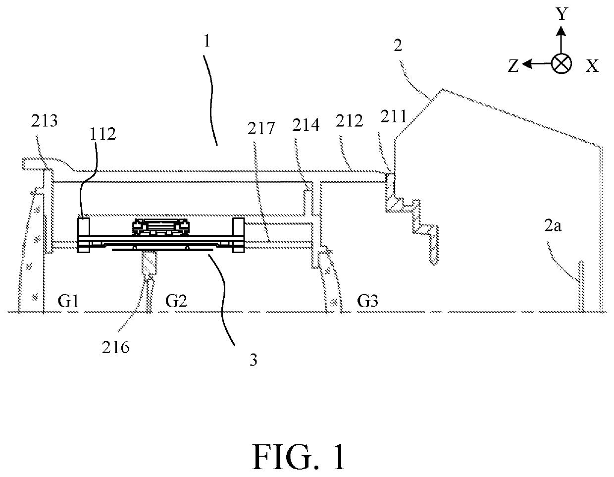
[0017]FIG. 1 is a structural diagram of an image pickup apparatus including a lens barrel (driving apparatus) 1 which is an illustrative driving apparatus mounted with a vibration wave motor 3 according to this embodiment. Since the lens barrel 1 has a substantially rotationally symmetric shape, FIG. 1 illustrates only an upper half of the lens barrel 1.

[0018]Although the lens barrel 1 is detachably attached to the camera body 2 in this embodiment, the lens barrel 1 may be integrated with the camera body 2.

[0019]An image sensor 2a is provided in the camera body 2. A mount 211 of the camera body 2 has a bayonet unit configured to attach the lens barrel 1 to the camera body 2.

[0020]The lens barrel 1 has a fixed cylinder 212 that contacts a flange unit of the mount 211. The fixed cylinder 212 and the mount 211 are fixed by screws (not shown). A front lens barrel 213 that holds a lens G1 and a rear lens barrel 214 that holds a lens G3 are fixed to the fixed cylinder 212.

[0021]The lens b...

second embodiment

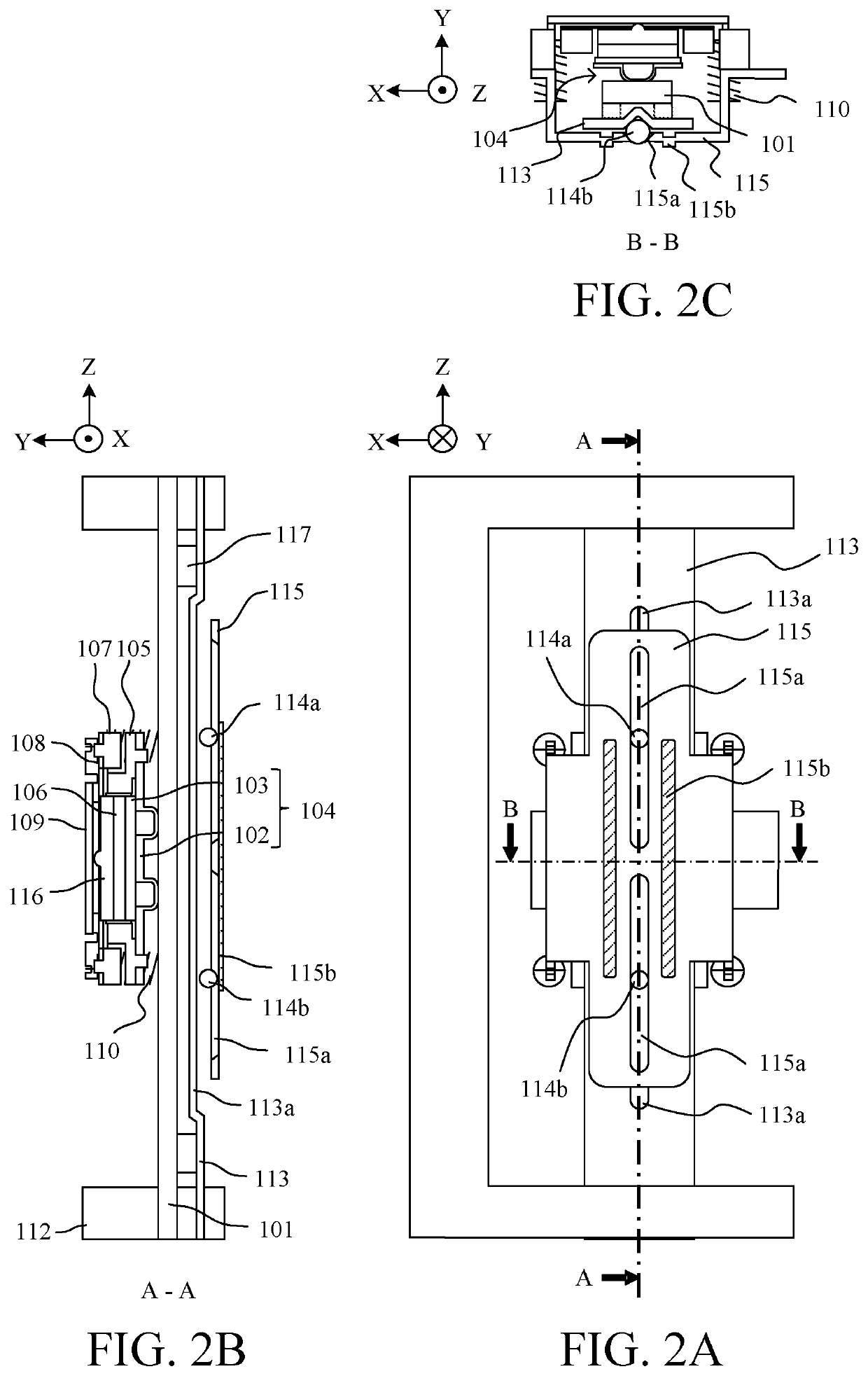
[0049]FIGS. 6A to 6C are structural diagrams of a vibration wave motor 3 according to this embodiment. FIG. 6A illustrates the vibration wave motor 3 viewed from the Y-axis direction. FIG. 6B is a sectional view of the vibration wave motor 3 taken along a line A-A in FIG. 6A. FIG. 6C is a sectional view taken along a line B-B in FIG. 6A of the vibration wave motor 3. This embodiment will discuss only the difference from the first embodiment, and a description of the common structure will be omitted.

[0050]In this embodiment, the movable-side guide member 115 includes three movable-side guide portions (guide portions) 115a with V-grooves. The fixed-side guide member 113 includes a fixed-side guide portion 113a with one V-groove and one flat surface. The balls (rollers) 114a, 114b, and 114c are sandwiched between the fixed-side guide portion 115a and the fixed-side guide portion 113a. The fixed-side guide member 113, the balls 114a, 114b, and 114c, and the movable-side guide member 115...


PUM


Abstract

A vibration wave motor includes a vibrator including a piezoelectric element and a vibratory plate, a friction member configured to make a frictional contact with the vibrator, a pressurizer configured to press the vibrator and the friction member against each other, and a guide unit configured to guide a relative movement between the vibrator and the friction member. The guide unit includes a plurality of rollers configured to move relative to the pressurizer, and a guide member that includes a guide portion, the guide portion being configured to extend along a relative movement direction between the vibrator and the friction member and to guide the plurality of rollers. The guide member includes a reinforcer configured to extend along the relative movement direction near a roller closest to a center position of a pressing force by the pressurizer.

Description

BACKGROUND OF THE INVENTIONField of the Invention[0001]The present invention relates to a vibration wave motor, and a driving apparatus having the same.Description of the Related Art[0002]Conventional vibration wave motors compressively energize a vibrator that serves as a driving source against a friction member, and extract a driving force using a frictional force generated by the compressive energization. The extracted driving force is guided in a desired guide direction by a guide unit, and a vibrator and the friction member are driven relative to each other in the guide direction. The guide unit includes a roller and the like so as not to generate an unnecessary load due to the pressing force other than the contact friction between the vibrator and the friction member. The guide unit has a guide member having a guide portion extending in the guide direction. In order to increase the driving amount, it is necessary to increase an extending amount of the guide portion in the guid...

Claims


Application Information

Patent Timeline
IPC IPC(8): H02N2/08H02N2/02H02N2/00
CPCH02N2/08H02N2/0055H02N2/001H02N2/026H02N2/006G02B7/08
Inventor YAMAMOTO, YASUFUMI
Owner CANON KK
Learn More