Driving Force Transmitter, Sheet Feeding Unit, and Image Forming Apparatus

a technology of driving force transmitter and feeding unit, which is applied in the direction of mechanical actuated clutches, electrographic processes, instruments, etc., can solve the problems of large electromagnetic size, and achieve the effect of increasing the amount of electric power consumed and increasing the driving for

Active Publication Date: 2018-03-22
BROTHER KOGYO KK
View PDF0 Cites 3 Cited by
  • Summary
  • Abstract
  • Description
  • Claims
  • Application Information

AI Technical Summary

Benefits of technology

[0005]With the electromagnetic clutch at the position between the main motor and the conveyer roller pair, and with the electromagnetic clutch to switch on or off of the driving force between the main motor and the conveyer roller pair, the electromagnetic clutch may require a certain amount of electric power to be supplied constantly while the conveyer roller pair is being driven. Further, in order for the driving force to be transmitted through the electromagnetic clutch to substantially move the conveyer roller pair, a substantial size of the electromagnetic may be required. In other words, when a load to drive the conveyer roller pair is larger, a larger or a more powerful electromagnetic clutch that may transmit the larger amount of driving force may be required; therefore, an amount of the electric power to be consumed may be increased.

Problems solved by technology

Further, in order for the driving force to be transmitted through the electromagnetic clutch to substantially move the conveyer roller pair, a substantial size of the electromagnetic may be required.

Method used


Image

  • Driving Force Transmitter, Sheet Feeding Unit, and Image Forming Apparatus
  • Driving Force Transmitter, Sheet Feeding Unit, and Image Forming Apparatus
  • Driving Force Transmitter, Sheet Feeding Unit, and Image Forming Apparatus

Examples


Embodiment Construction

[0020]Hereinafter, an embodiment of the present disclosure will be described with reference to the accompanying drawings.

[0021][Overall Configuration of Image Forming Apparatus]

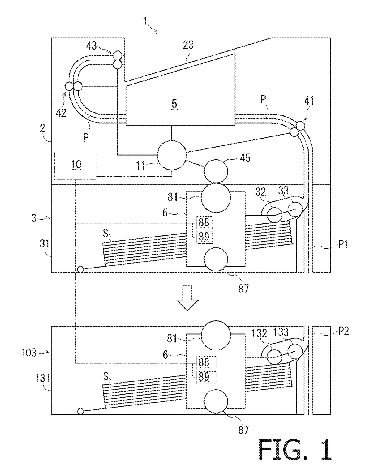
[0022]An image forming apparatus 1 includes, as shown in FIG. 1, a housing 2, a motor 11, an image forming unit 5, a sheet feeder 3, and a controller 10. The motor 11 may generate a driving force to drive the image forming unit 5, and the image forming unit 5 driven by the driving force may form an image on a sheet S. The sheet feeder 3 may feed sheets S to the image forming unit 5. The controller 10 may control behaviors of devices in the image forming apparatus 1 including the motor 11 and the sheet feeder 3. Further, an extension sheet feeder 103, which is formed separately from the image forming apparatus 1 and may feed sheets S to the image forming unit 5, is additionally attachable to the image forming apparatus 1.

[0023]In the following description, directions related the image forming apparatus 1 and e...


PUM


Abstract

A driving force transmitter, including a coupling member, a cam member, an electromagnetic clutch, a sensor, and a controller, is provided. The coupling member arranged between a driving source and a driven device includes a first shaft, a second shaft, a stationary coupling member, and a movable coupling member which is movable between a separating position and an engaging position. The cam member is rotatable to move the movable coupling member. The electromagnetic clutch connects the cam member with the driving source when electrically powered and disconnects the cam member when not electrically powered. The sensor detects rotational positions of the cam member. The controller switches the electricity to the electromagnetic clutch according to the rotational positions of the cam member.

Description

CROSS REFERENCE TO RELATED APPLICATION[0001]This application claims priority from Japanese Patent Application No. 2016-183493, filed on Sep. 20, 2016, the entire subject matter of which is incorporated herein by reference.BACKGROUNDTechnical Field[0002]An aspect of the present disclosure is related to a driving force transmitter for transmitting a driving force, and an extension sheet feeding unit and an image forming apparatus having the driving force transmitter.Related Art[0003]An image forming apparatus, such as a printer, a copier, and a multifunction peripheral, having a driving source and a drivable device driven by a driving force from the driving source, is known. The driving force from the driving source may be transmitted to the drivable device through an electromagnetic clutch, which may switch the driving force on and off.[0004]For example, an image forming apparatus may have a conveyer roller pair as a drivable device, which may be driven to be rotated by a driving for...

Claims


Application Information

Patent Timeline
Patent Type & Authority Applications(United States)
IPC IPC(8): F16D23/12F16D27/10B65H3/06B65H7/00G03G15/00
CPCF16D23/12F16D27/10B65H3/0669B65H2403/724G03G15/6529F16D2023/123B65H7/00G03G15/757G03G21/1857G03G21/186G03G21/1647G03G2215/00679G03G2221/1657B65H2402/10
Inventor HASHIMOTO, YOHEI
Owner BROTHER KOGYO KK
Why Eureka
Try Eureka