Battery electrode structure and method for manufacture thereof

a battery electrode and electrode structure technology, applied in primary cell electrodes, non-aqueous electrolyte accumulator electrodes, coatings, etc., can solve the problems of reducing the electrode capacity and non-uniform consumption of the depolarizer, and achieve the effects of increasing the energy density of chemical sources, reducing porosity, and increasing electrode density

Inactive Publication Date: 2006-02-02
OXIS ENERGY
View PDF72 Cites 107 Cited by
  • Summary
  • Abstract
  • Description
  • Claims
  • Application Information

AI Technical Summary

Benefits of technology

[0020] On the one hand, an increase in the density of the electrodes (decrease in porosity) produces an increase of the energy density of chemical sources of electrical energy. On the

Problems solved by technology

The applicant has found that the non-uniform distribution of the electrochemical reaction rate over the electrode

Method used


Image

  • Battery electrode structure and method for manufacture thereof
  • Battery electrode structure and method for manufacture thereof

Examples


example 1

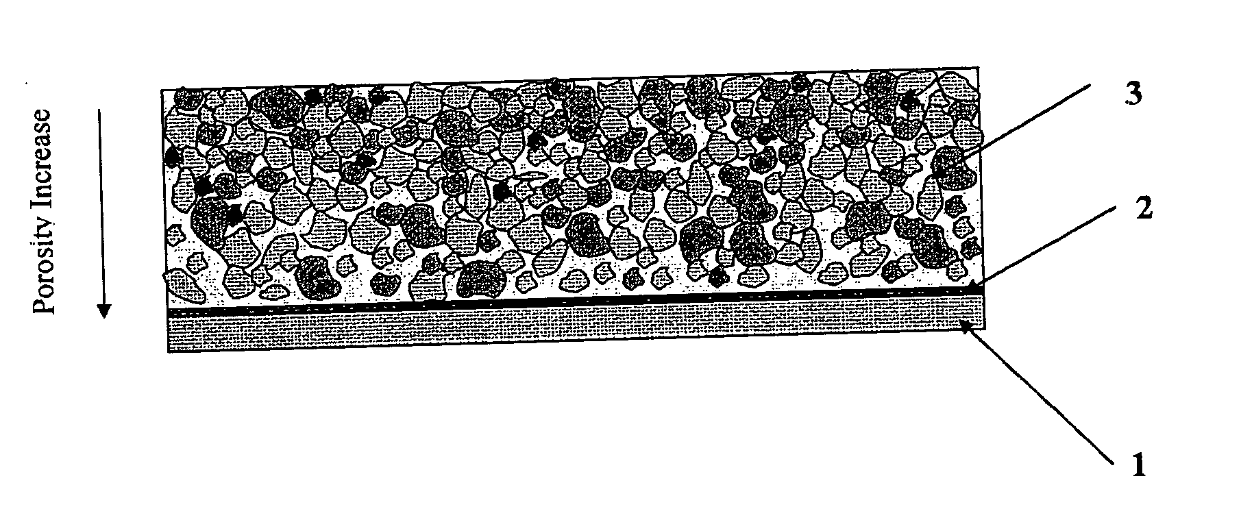
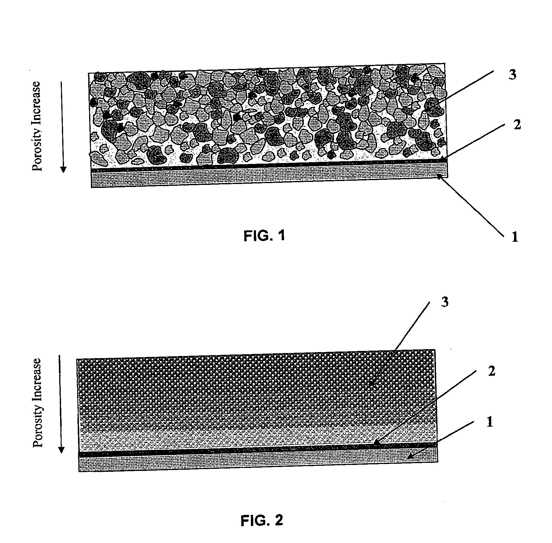
[0077] Cathode active layers with a composition by weight of 70% elemental sulphur (available from Fisher Scientific, Loughborough, UK), 10% conductive carbon black (Ketjenblack® EC-600JD, available from Akzo Nobel Polymer Chemicals BV, Netherlands) and 20% polyethylene oxide (PEO, 4,000,000 molecular weight, available from Sigma-Aldrich Company Ltd, Gillingham, UK) were prepared by the following method. A mixture of dry components was ground in a homogenising system Microtron® MB550 for 10-15 minutes. Acetonitrile was added as a solvent to the obtained mixture. The resulting liquid suspension or slurry was mixed for 15-20 hours with a laboratory stirrer DLH. The solids content of the slurry was 10-15 weight percent. The resulting mixture was cast by an automatic film applicator Elcometer® SPRL with a doctor blade onto one side of an 18 micrometre thick conductive carbon coated aluminium foil (available from InteliCoat®, South Hadley, Mass.) as a current collector and substrate. The...

example 2

[0079] The slurry from Example 1 was cast by an automatic film applicator Elcometer® SPRL with onto one side of an 18 micrometre thick conductive carbon coated aluminium foil (available from InteliCoat®, South Hadley, Mass.) as a current collector and substrate. The doctor blade gap was different from that used in Example 1. The coating was dried under ambient conditions for 20 hours and then dried under vacuum at 50° C. for five hours.

[0080] The resulting dry cathode active layer had a thickness of about 21 micrometres with a loading of the cathode composition of 1.35 mg / cm2. The volumetric density of the electroactive coating was about 636 mg / cm3. The porosity of the cathode active layer was 65%.

example 3

[0081] A second layer of the slurry was cast by an automatic film applicator Elcometer® SPRL on top of the solid composite cathode from Example 1. The new coating was dried under ambient conditions for 20 hours and then dried under vacuum at 50° C. for five hours.

[0082] The resulting overall thickness of the dry cathode active layer was 25 micrometres with a loading of the cathode composition of 2.23 mg / cm2. The volumetric density of two layers of the electroactive coating was about 890 mg / cm3. The porosity of the cathode active layer was 55%.


PUM


Abstract

There are disclosed solid composite electrodes with electrode active layers that include an electrode active material, an optional election conductive material, an optional binder and other optional additives. The solid composite electrodes are formed by the deposition of an electrode composition (slurry) onto a current collector in one or many layers. The electrode structure may be characterised by a porosity of the electrode composition layer that decreases in a direction from the back side of the layer (close to the current collector) towards the outer side of the layer. The gradient of the decrease in the porosity is controlled by the content of solid substance in the slurry, by the composition of the solvent in the slurry, by the temperature of the layer drying after deposition, as well as by the pressing or calendering conditions for each layer. The electrode structures can be used in for example chemical sources of electric energy such as primary (non-rechargeable) as well as secondary (rechargeable) batteries.

Description

PRIOR APPLICATION DATA [0001] The present application claims benefit from prior U.S. provisional application Ser. No. 60 / 591,083 filed on Jul. 27, 2004 and entitled “Improvements Relating to Electrode Structures in Batteries”, and UK application 0416708.6 filed on 27th Jul. 2004, each incorporated herein by reference in its entirety.TECHNICAL FIELD [0002] The present invention relates to chemical sources of electric energy comprising positive electrodes (cathodes) and negative electrodes (anodes). In particular, the invention relates to rechargeable (secondary) and non-rechargeable (primary) battery cells comprising a negative electrode providing ions (anode), an intermediate separator element containing an electrolyte solution or a hard polymer electrolyte through which ions from a source electrode material move between cell electrodes during charge and discharge cycles of the cell, and a positive electrode (cathode) comprising an electrode depolarizer substance (cathode active mat...

Claims


Application Information

Patent Timeline
IPC IPC(8): H01M4/02H01M4/60H01M4/58H01M4/48H01M4/62B05D5/12H01M4/13H01M4/131H01M4/133H01M4/136H01M4/139H01M4/1391H01M4/1393H01M4/1397H01M4/50H01M4/505H01M10/0525H01M10/0565H01M10/36
CPCH01M4/13H01M4/06H01M4/133H01M4/136H01M4/139H01M4/1391H01M4/1393H01M4/1397H01M4/366H01M4/382H01M4/505H01M4/581H01M4/60H01M4/62H01M10/0525H01M10/0565H01M2004/021Y02E60/122H01M4/131Y02E60/10
Inventor KOLOSNITSYN, VLADIMIRKARASEVA, ELENA
Owner OXIS ENERGY
Why Eureka
Try Eureka