Implantable power management system

Inactive Publication Date: 2000-12-26
EXONIX
View PDF9 Cites 102 Cited by
  • Summary
  • Abstract
  • Description
  • Claims
  • Application Information

AI Technical Summary

Problems solved by technology

Furthermore, the prior art circuitry is incapable of properly regulating the charge/discharge cycles of new implantable-grade power sources, such as a Lithium-Ion cell battery.
One limitation of a capacitive power source is the small amount of charge that it can hold relative to an electrochemical rechargeable cell.
In the case of a Super-capacitor powered Implantable Medical Device, when the device requires very high power consumption, its power source must be recharged very freque

Method used


Image

  • Implantable power management system
  • Implantable power management system
  • Implantable power management system

Examples


Embodiment Construction

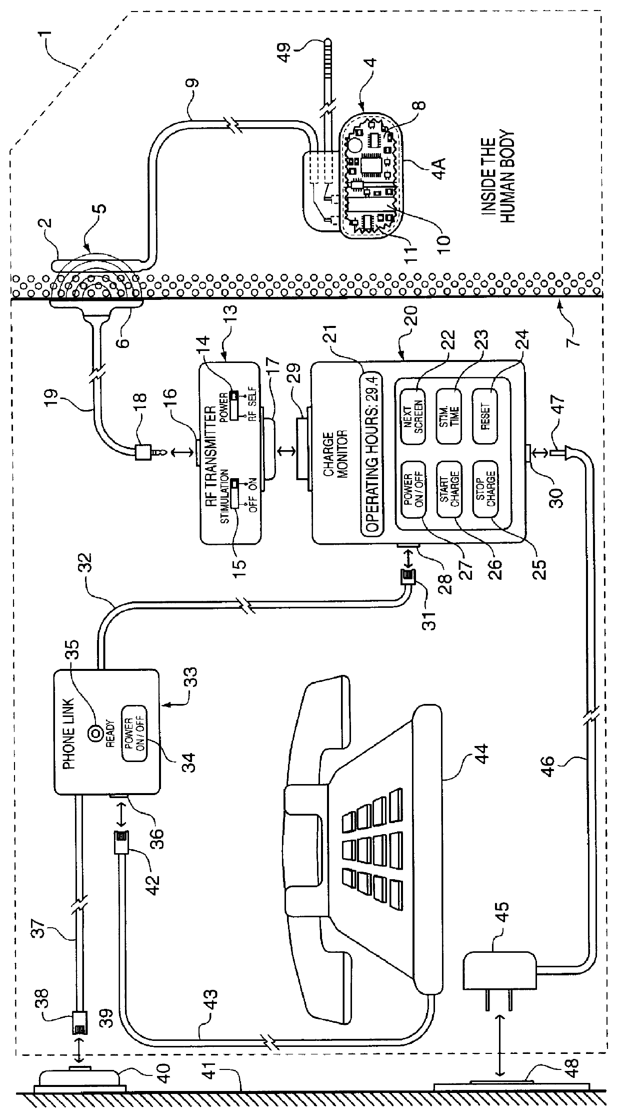
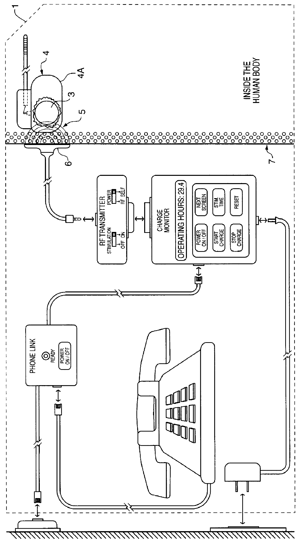
FIG. 1 illustrates the power management system 1 of the present invention. The system 1 utilizes an implanted RF receiving antenna 2 located outside of an Implantable Medical Device 4. This RF receiving antenna 2 is used for capturing RF electrical energy 5 being transmitted by an RF Transmitting Antenna 6 located outside the human body tissue 7. The Implanted Medical Device 4 is typically enclosed in a hermetic titanium housing 4A in order to prevent intrusion of the body fluids which would permanently damage its sensitive electronic circuitry 8. This titanium housing 4A significantly attenuate and reduces the RF energy that can be coupled through the titanium enclosure 4A. Therefore, in FIG. 1, the RF receiving antenna 2 is placed outside of the Implanted Medical Device 4 but inside the human body, using insulated wires in a cable 9 to bring the coupled RF energy to the Implanted Medical Device 4 in order to recharge its power source 10.

FIG. 2 shows an embodiment of the Power Mana...


PUM


Abstract

The method and system for managing power supplied from a charging circuit to a power source in an implantable medical device comprises the steps of and circuitry for: measuring the current drain of the medical device; measuring the elapsed time since the last full charge of a power source of the device; calculating the actual capacity of the power source (corrected for fade) based on the variable of current drain and the variable of elapsed time; calculating the operating time based on the variable of current drain and the variable of the actual capacity of the power source; measuring the voltage of the power source; signaling the medical device when the power source voltage has reached a certain low value which requires disconnection from the power source; disconnecting, during discharging, the power source from the medical device upon the power source reaching a certain low voltage in order to prevent deep discharging of the power source and subsequent damage; precisely limiting the charging voltage to the power source in order to prevent overcharging beyond safe limits; disconnecting, during charging, the power source from the charging circuit upon the power source reaching a certain high voltage in order to prevent overcharging of the power source and subsequent damage; sensing when the electromagnetic waves being transmitted by an RF transmitter/charger induce a voltage level above a certain value at an RF receiver of the implanted power management system; reconnecting power supply inputs of the medical device to the power source upon sensing this induced high voltage level; monitoring the temperature of the power source during charging and discharging; disconnecting the charging circuitry from the power source if the temperature of the power source raises above a certain level during charging; reconnecting the charging circuitry to the power source when the temperature of the power source drops below a certain low value during charging; disconnecting the implanted medical device from the power source if the temperature of the power source raises above a certain level during discharging; and, reconnecting the medical device to the power source when the temperature of the power source drops below a certain low value during discharging.

Description

1. Field of the InventionThe present invention relates to a method and circuitry for safely regulating the charge and discharge cycles of implantable grade, rechargeable power sources, utilizing inductively coupled radio frequency energy. Patient safety and power source longevity are vastly improved by the method and circuitry of the system of the present invention. Such safety and longevity are obtained by the steps of: (1) measuring and recording, each charge / discharge cycle, to obtain the corrected capacity of the power source in order to calculate and display, upon interrogation, the remaining operating time of the implanted device, (2) providing within the implanted medical device circuitry for disconnecting the power source upon reaching a pre-selected low voltage in order to prevent deep-discharging the power source below safe limits, (3) providing circuitry for using variable constant current charge rates, (4) providing circuitry for switching to constant voltage to top-off ...

Claims


Application Information

Patent Timeline
IPC IPC(8): A61N1/378A61N1/372H02J7/00H02J17/00A61N1/37
CPCA61N1/3708A61N1/3787H02J17/00H02J7/0063H02J7/0031H02J50/20H02J50/90H02J7/0029H02J7/00302H02J7/00308H02J7/007194H02J7/007182H02J7/00309H02J7/00306H02J2310/23
Inventor ECHARRI, GUILLERMOECHARRI, ROBERTOBARRERAS, SR., FRANCISCO JOSEJIMENEZ, OSCAR
Owner EXONIX
Why Eureka
Try Eureka