Positive electrode material for lithium secondary battery and lithium secondary battery using the same

Active Publication Date: 2005-06-30
HITACHI VEHICLE ENERGY
View PDF1 Cites 106 Cited by
  • Summary
  • Abstract
  • Description
  • Claims
  • Application Information

AI Technical Summary

Benefits of technology

[0015] According to the present invention, a nonaqueous lithium secondary battery that has superior cycle life and safety and has improved internal resistance of the battery under low tem

Problems solved by technology

LiNiO2 in which Ni is used, which is a layered positive electrode material, the Ni being more readily reduced to result in a divalent state than Co or Mn, tends to cause lithium defects due to volatilization of lithium salt in the material upon high-temperature calcinatio

Method used


Image

  • Positive electrode material for lithium secondary battery and lithium secondary battery using the same
  • Positive electrode material for lithium secondary battery and lithium secondary battery using the same
  • Positive electrode material for lithium secondary battery and lithium secondary battery using the same

Examples


embodiment

[0034] In the following, examples and comparative examples regarding the present invention are described. The present invention is not limited to the following examples.

example 1

[0035] (Preparing Positive Electrode Material)

[0036] In the example, manganese dioxide, cobalt oxide, nickel oxide, and lithium carbonate were used as raw materials. After being weighed such that the element ratio was equivalent to a predetermined value, ethanol was added, and the materials were ground by a planetary ball mill in wet condition for five hours, and then mixed. Ater the powders were calcined at 1000° C. for 10 to 30 hours, a layered positive electrode material (1) was gained by crushing the powders.

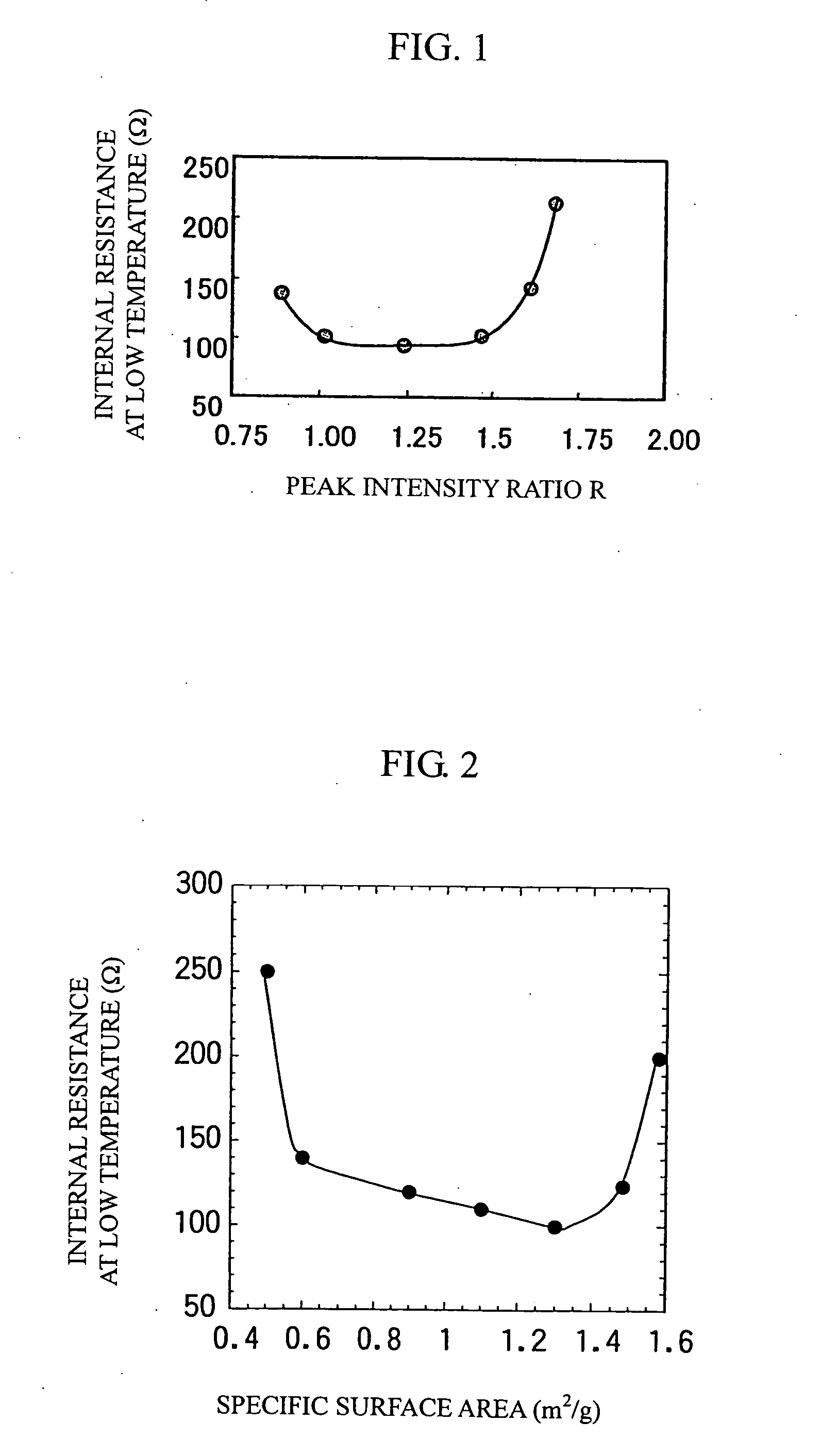
[0037] The gained layered positive electrode material (1) was ground by an agate mortar and X-ray diffraction was carried out using Cu—Kα as a radiation source. The measurement conditions were: 50 kV of-tube voltage; 200 mA of tube current; and 0.01° / second of diffraction speed. The intensity ratio R was obtained by dividing the diffraction peak intensity of a (003) plane by the diffraction peak intensity of a (104) plane. In this case, R was 1.2. Also, the peak intensity ...

example 2

[0061] In this example, positive electrode materials (4) to (11) with the compositions shown in Table 1 (in which the transition metals were substituted with Al, B, Fe, Cu, Mg, Zn, Ga, or Si) were prepared in the same procedure as in Example 1, and these materials were subjected to X-ray diffraction and BET specific surface area measurement in the same procedure as in Example 1. The raw materials for the elements for substitution were oxides, which were mixed with other oxide raw materials using a planetary ball mill.

[0062] Positive electrode materials (4), (5), (6), (7), (8), (9), (10), and (11) were prepared by substituting the transition metals with Al, B, Fe, Cu, Mg, Zn, Ga, and Si, respectively. Table 1 shows their peak intensity ratios R and BET specific surface areas, which were substantially identical to those of the positive electrode material (1) in Example 1.

[0063] Test batteries were then prepared using the positive electrode materials (4) to (11) in the same manner as...


PUM


Abstract

A positive electrode material for a nonaqueous lithium secondary battery and a lithium secondary battery that has superior cycle life and safety and reduced internal resistance of the battery at low temperature is provided. The positive electrode material for a nonaqueous lithium secondary battery comprise a layered structured complex oxide expressed by a composition formula LiaMnxNiyCozMαO2, where 0<a≦1.2, 0.1≦x≦0.9, 0≦y≦0.44, 0.1≦z≦0.6, 0.01≦α≦0.1, and x+y+z+α=1. A diffraction peak intensity ratio between the (003) plane and the (104) plane (I(003)/I(104)) in an X-ray powder diffractometry using a Cu—Kα line in the X-ray source is not less than 1.0 and not more than 1.5.

Description

BACKGROUND OF THE INVENTION [0001] 1. Field of the Invention [0002] The present invention relates to a layer structured positive electrode material for a large lithium secondary battery that uses nonaqueous electrolytic solution, a positive plate, and to a lithium secondary battery. More specifically, the present invention relates to improvement of Li ion conductivity of a positive electrode material for a lithium secondary battery at low temperature. [0003] 2. Background Art [0004] There has been demand for developing high power and high energy density batteries for power supply of electric automobiles and hybrid automobiles as environmentally friendly vehicles. Since lithium secondary batteries that use nonaqueous electrolytic solution have high battery voltage and high energy density as batteries used for power supply, various sectors have been industriously developing them. Also, batteries for automobiles are required to have long operating life, high power output, stable voltag...

Claims


Application Information

Patent Timeline
IPC IPC(8): H01M10/05C01G1/02C01G53/00H01M2/02H01M4/131H01M4/36H01M4/505H01M4/525H01M4/62H01M10/0525
CPCH01M2/023H01M4/0404H01M4/133H01M4/1391H01M4/366H01M4/505Y02T10/7011H01M4/625H01M10/0525H01M10/0587H01M2004/028Y02E60/122H01M4/525H01M50/56Y02E60/10Y02T10/70
Inventor YUASA, TOYOTAKAKASAI, MASAHIRO
Owner HITACHI VEHICLE ENERGY
Why Eureka
Try Eureka