Method for producing electrode laminate and electrode laminate
a technology of electrode laminate and electrode, which is applied in the direction of sustainable manufacturing/processing, paper/cardboard containers, cell components, etc., to achieve the effect of reducing the capacity density of batteries, simple and easy method, and high adhesiveness
- Summary
- Abstract
- Description
- Claims
- Application Information
AI Technical Summary
Benefits of technology
Problems solved by technology
Method used
Image
Examples
first embodiment
1. First Embodiment
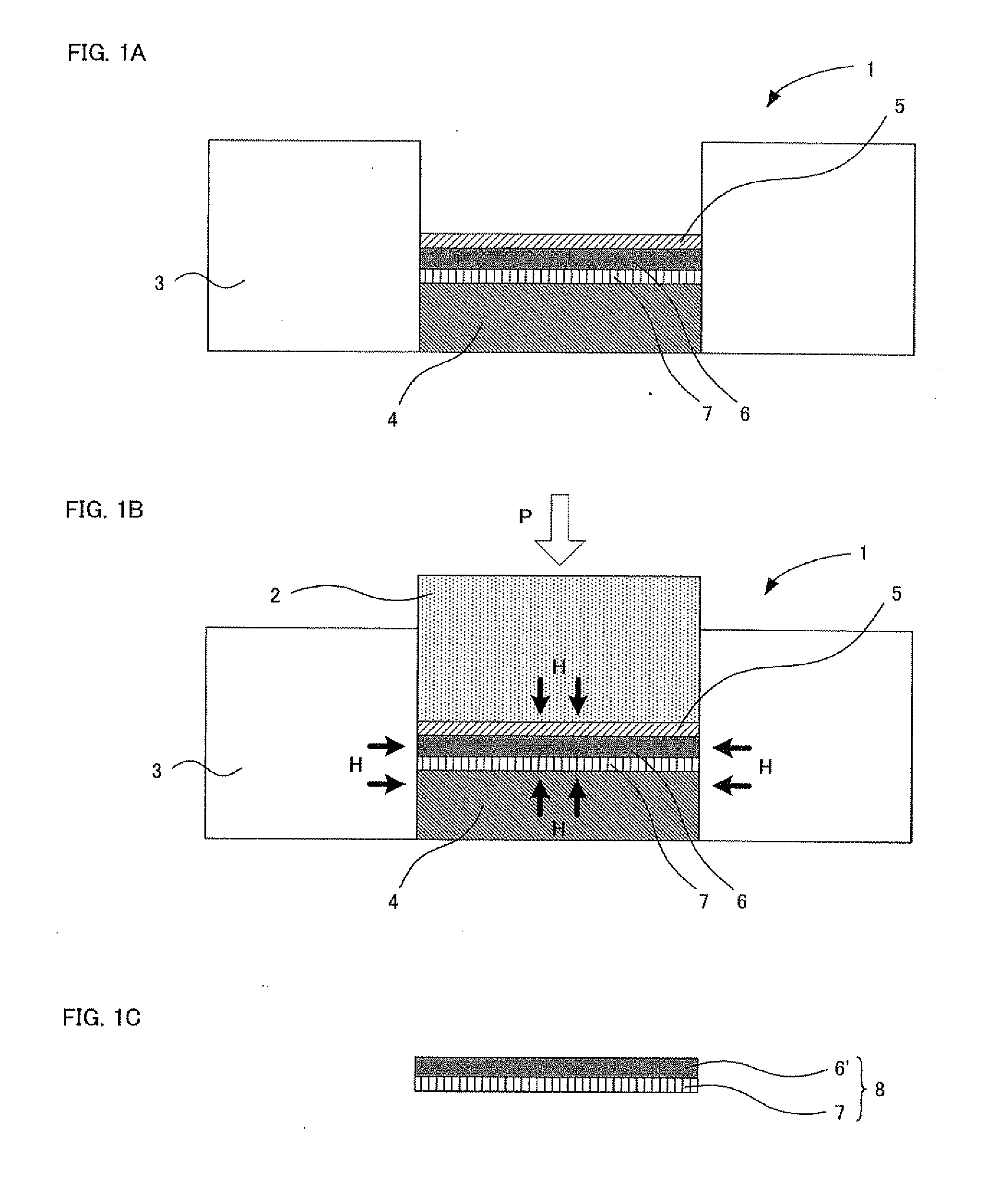
[0042]First, the method for producing an electrode laminate according to the first embodiment of the present invention will be described. The method for producing an electrode laminate according to the first embodiment comprises of the steps of: laminating an electrode layer forming composition, which contains at least a sulfide-based solid electrolyte and an active material and no binding agent, on a current collector using aluminum as a material; and heating the current collector and the electrode layer forming composition at a temperature of not less than 60° C. and adhering them.
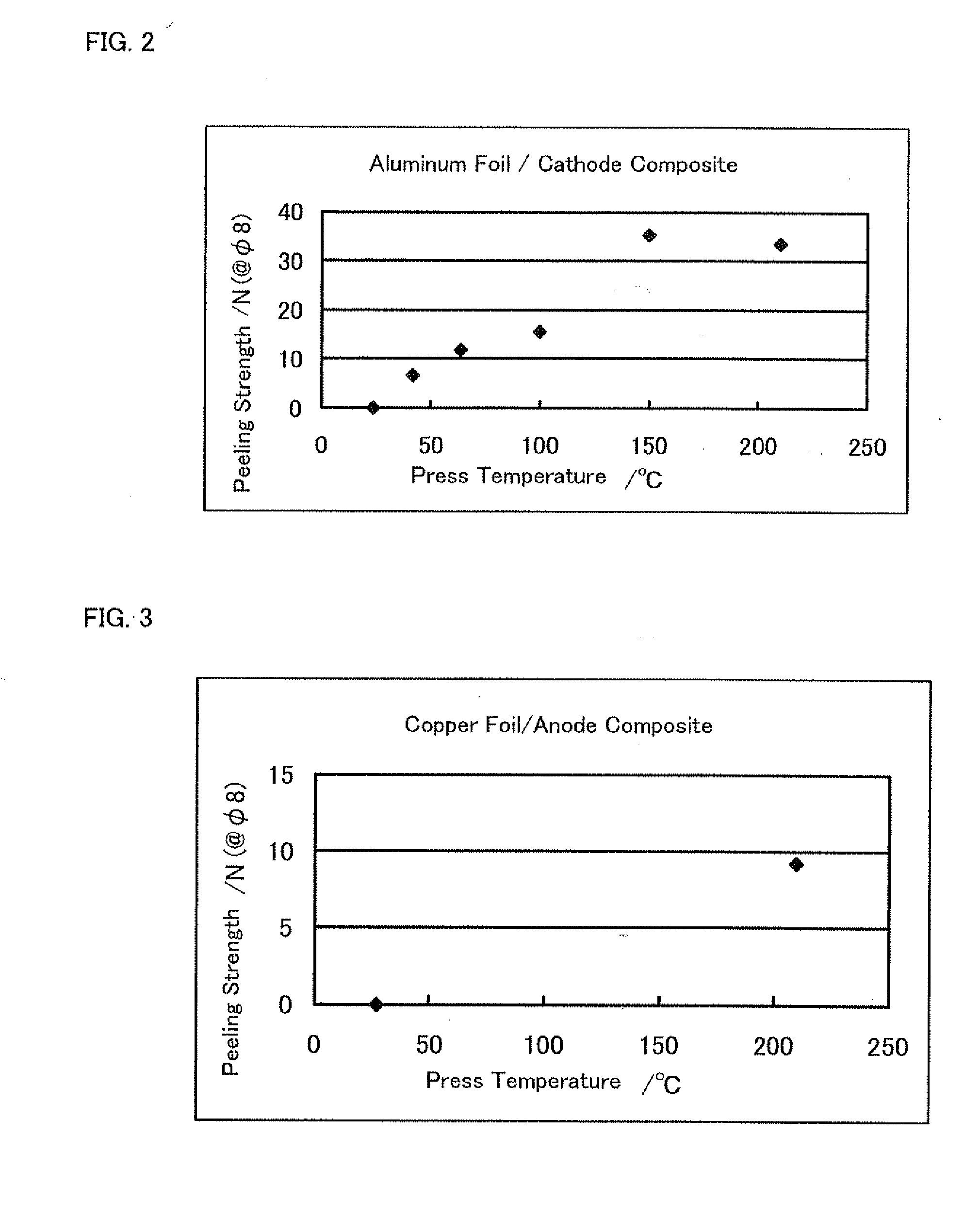
[0043]According to the present embodiment, the current collector using aluminum as the material and the electrode layer forming composition, which contains at least the sulfide-based solid electrolyte and the active material and no binding agent, are adhered by heating at the temperature of not less than 60° C., whereby aluminum atoms derived from the current collector are diffused in ...
second embodiment
2. Second Embodiment
[0086]Next, the method for producing an electrode laminate of the second embodiment of the present invention will be described. The method for producing an electrode laminate of the second embodiment comprises the steps of: laminating an electrode layer forming composition, which contains at least a sulfide-based solid electrolyte and an active material and no binding agent and no solvent, on a current collector; and heating the current collector and the electrode layer forming composition.
[0087]According to the present embodiment, by virtue of not containing the solvent, composition distribution of the electrode layer forming composition does not occur at an interface between the current collector and the electrode layer, and the sulfide-based solid electrolyte is not unevenly distributed. Therefore, the adhesiveness between the current collector and the electrode layer can be increased. Further, the current collector and the electrode layer forming composition ...
example 1
[0137]First, an aluminum foil with a thickness of 0.015 mm was hollowed out to obtain a single aluminum foil having a shape of a circle of φ11.28 mm to provide a current collector. Likewise, a SUS foil with a thickness of 0.015 mm was hollowed out to obtain a SUS foil having a shape of a circle of φ11.28 mm to provide a release substrate.
[0138]Next, the current collector was disposed in a press molding machine, and a cathode layer forming composition, in which a sulfide-based solid electrolyte (Li2S—P2S5 compound) and a cathode active material (LiCoO2) were mixed in a mass ratio of Li2S—P2S5 compound:LiCoO2=3:7, was laminated on the current collector, and the release substrate was further disposed on the cathode layer forming composition. The obtained laminate was held by the press molding machine to be subjected to application of a pressure of 2 ton / cm2 from above and below.
[0139]Next, the press molding machine was heated in an electric furnace so that the press temperature was 150...
PUM
| Property | Measurement | Unit |
|---|---|---|
| temperature | aaaaa | aaaaa |
| temperature | aaaaa | aaaaa |
| temperature | aaaaa | aaaaa |
Abstract
Description
Claims
Application Information
 - R&D
- Intellectual Property
- Life Sciences
- Materials
- Tech Scout
- Unparalleled Data Quality
- Higher Quality Content
- 60% Fewer Hallucinations
Browse by: Latest US Patents, China's latest patents, Technical Efficacy Thesaurus, Application Domain, Technology Topic, Popular Technical Reports.
© 2025 PatSnap. All rights reserved.Legal|Privacy policy|Modern Slavery Act Transparency Statement|Sitemap|About US| Contact US: help@patsnap.com


