Device and method for scanning measurement of the distance to an object

a technology of distance measurement and device, which is applied in the direction of measurement devices, using reradiation, instruments, etc., can solve the problems of damage to optical switches, unavoidable high intensities at the inputs of distribution matrices, etc., and achieves short switching time, lower insertion loss, and higher insertion loss

Active Publication Date: 2021-11-25
SCANTINEL PHOTONICS GMBH
View PDF0 Cites 3 Cited by
  • Summary
  • Abstract
  • Description
  • Claims
  • Application Information

AI Technical Summary

Benefits of technology

[0010]The comparatively small distribution matrices of the individual processing units also have advantages for the output signals propagating in the opposite direction. Since they only pass through few optical switches in the distribution matrix, high intensities do not have to be applied at the input of the distribution matrices to ensure sufficient intensities at the output of the free space couplers. In the conventional devices of this type, which have large distribution matrices, high intensities at the inputs of the distribution matrices are unavoidable, since it is only ensured by high intensities that the output signals will still have a sufficiently high intensity even after passing a large number of optical switches when they exit from the free space couplers. However, very high intensities can damage the optical switches and are therefore to be avoided.
[0022]If there are no special requirements for the sequence in which the free space couplers from the switching matrix are connected to the light source, it is sufficient if a single first optical switch having a short switching time and higher insertion loss is arranged on the lowest level of the tree and exclusively second optical switches are arranged on all other levels, which are slower but have a lower insertion loss. In a distribution matrix having 16 outputs, the optical signals pass through, for example, four 1×2 switches, of which according to the invention, however, only the first switch passed through in the light path at the lowest level has to have a short switching time and therefore has a higher insertion loss. Due to the arrangement according to the invention of different switch types, the insertion loss of the entire distribution matrix can be reduced enough that the signals detected by the detector have a sufficiently high signal-to-noise ratio. The speed of the entire distribution matrix is only limited by the switching time of the fast first switch. As long as the second slow switches have a switching time which is shorter than the measurement frequency, the second optical switches can be optimized for minimal insertion loss.

Problems solved by technology

In the conventional devices of this type, which have large distribution matrices, high intensities at the inputs of the distribution matrices are unavoidable, since it is only ensured by high intensities that the output signals will still have a sufficiently high intensity even after passing a large number of optical switches when they exit from the free space couplers.
However, very high intensities can damage the optical switches and are therefore to be avoided.

Method used


Image

  • Device and method for scanning measurement of the distance to an object
  • Device and method for scanning measurement of the distance to an object
  • Device and method for scanning measurement of the distance to an object

Examples


Embodiment Construction

pplication Example

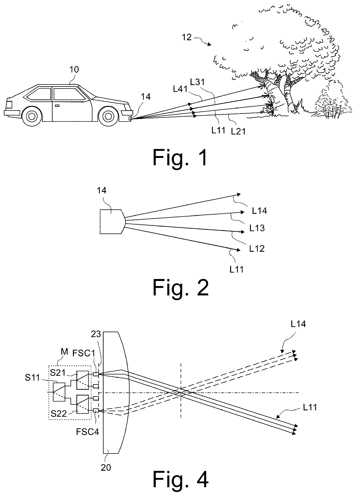
[0035]FIG. 1 shows a schematic side view of a vehicle 10, which approaches an object 12, which is a tree in FIG. 1. The vehicle 10 has at least one scanning device 14, which scans the environment lying ahead of the vehicle 10 with the aid of light beams L11, L21, L31, and L41, from which a three-dimensional image of the environment is calculated. In addition, the scanning device 14 determines the relative velocity in relation to the object 12. This information is important above all if the object 12 is another vehicle and also moves.

[0036]The items of information ascertained by the scanning device 14 about the environment lying ahead of the vehicle 10 can be used, for example, to assist the driver of the vehicle 10 in a manner assisting the driver in the vehicle control, by warning messages being generated if a collision of the vehicle 10 with the object 12 threatens. If the vehicle 10 drives autonomously, the items of information about the environment lying ahead ...


PUM

PropertyMeasurementUnit
wavelengthaaaaaaaaaa

Abstract

A device for scanning measurement of a distance to an object has a light source, which generates an optical output signal having a time-varying frequency. The device includes multiple optical processing units, which are connected optically in parallel to the light source. Each processing unit has an optical distribution matrix including multiple optical switches that distribute optical output signals selectively onto different optical waveguides. Optical output signals are outcoupled into the free space via free space couplers and optical output signals reflected on the object are coupled as optical measurement signals into the waveguides. A detector detects a superposition of the optical measurement signal and the optical output signal generated by the light source. A circulator directs optical output signals supplied by the light source to the distribution matrix and optical measurement signals coming from the distribution matrix to the detector.

Description

CROSS-REFERENCE TO RELATED APPLICATIONS[0001]The present application is a continuation of U.S. patent application Ser. No. 17 / 022,522 filed Sep. 16, 2020, which claims the benefit of European patent application 20176355.4 filed on May 25, 2020, both of which are incorporated herein by reference in their entireties.BACKGROUND OF THE INVENTION1. Field of the Invention[0002]The invention relates to a device and a method for scanning measurement of the distance to a moving or unmoving object on the basis of the FMCW-LiDAR technology. Such devices can be used, for example, in autonomously driving vehicles and can be implemented as photonic integrated circuits (PIC), which do not contain moving parts.2. Description of Related Prior Art[0003]A measurement principle known as FMCW-LiDAR is known for optical distance measurement, in which an optical signal having time-varying frequency (FMCW stands for frequency modulated continuous wave) is directed onto the object to be measured and detecte...

Claims


Application Information

Patent Timeline
Patent Type & Authority Applications(United States)
IPC IPC(8): G01S7/481G01S17/931G01S17/32G02F1/31
CPCG01S7/4817G01S17/931G02F1/31G01S7/4816G01S17/32G01S17/34G01S17/89G01S7/4917G01S7/4818H04Q11/0005H04Q2011/0015H04Q2011/0039
Inventor DAVYDENKO, VLADIMIR
Owner SCANTINEL PHOTONICS GMBH
Why Eureka
Try Eureka