
Solution Dispensing Device

Pending Publication Date: 2022-09-08
WISE ROBERT
View PDF13 Cites 0 Cited by
  • Summary
  • Abstract
  • Description
  • Claims
  • Application Information

AI Technical Summary

Benefits of technology

The solution dispensing device has an output selector that controls the amount of solution that comes out of it. This allows for more or less solution to be selected by the user.

Problems solved by technology

These cans produce a large amount of waste.
Even after the cans break down, the residual, potentially harmful interior material is then released into the soil or air.
This can cause further damage to an area of land.
Traditional aerosol cans use dangerous gases to pressurize the cans.
In some instances, these gases are only harmful to the overall environment.
In other instances, these gases are poisonous to humans.
These gases may cause damage to a body or even cause cancer.
These gases may even be deadly if inhaled.
The combination of gases and having sealed metal cans means that refilling these items is not an option.
Many times, solutions in these cans tend to separate over time.
This means that the solutions to be ed often change in consistency over time and become weaker.
This shaking is often unsuccessful and does not properly mix the solution.

Method used


Image

  • Solution Dispensing Device
  • Solution Dispensing Device
  • Solution Dispensing Device

Examples


Embodiment Construction

[0024]Reference is made herein to the attached drawings. Like reference numerals are used throughout the drawings to depict like or similar elements of the solution dispensing device. For the purposes of presenting a brief and clear description of the present invention, a preferred embodiment will be discussed as used for the solution dispensing device. The figures are intended for representative purposes only and should not be considered to be limiting in any respect.

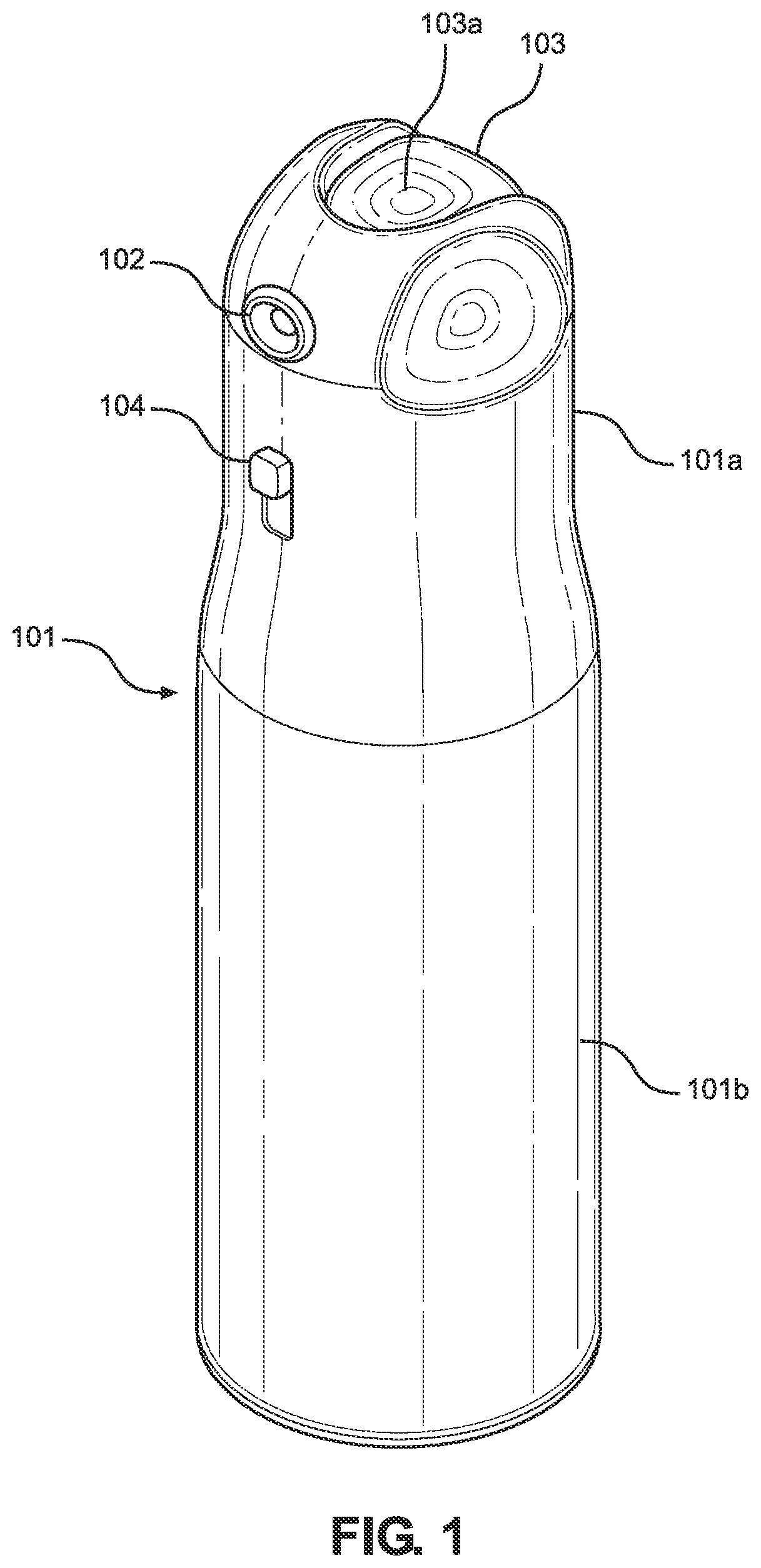
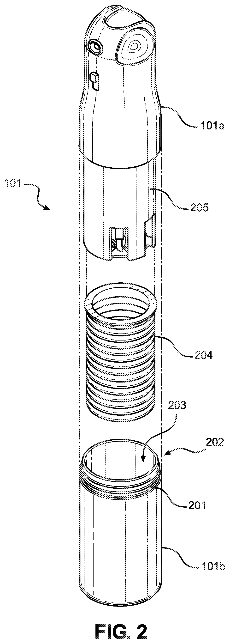
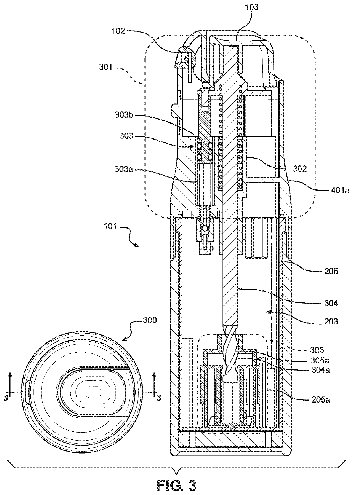
[0025]Referring now to FIG. 1, there is shown a perspective view of an embodiment of the solution dispensing device. The solution dispensing device is comprised of a housing 101 having an upper section 101a and a lower section 101b. The upper section 101a and the lower section 101b are secured together as will be described in the description of FIG. 2. In one embodiment, the housing 101 is a cylindrical housing. This will allow the device to be easily held in one hand. While other shapes are plausible as part of this d...


PUM


Abstract

A solution dispensing device includes a housing having an upper section and a lower section that seal when coupled, and an interior volume that functions as a refillable reservoir, the interior volume reservoir accessible via an aperture, whereby a refill cartridge containing a solute solution is deposited within the interior volume reservoir via an aperture, the solute solution and refill cartridge housing dissolving within varied measure of prescribed solvent added within the interior volume of the lower section reservoir. An actuator mechanism is configured to cause the mixed concentrate solution, which includes a combination of a dissolved solute solution, a dissolved refill cartridge, and a solvent, deposited within the refillable solution reservoir, to be drawn through and held within the actuator mechanism of the device, readied to be dispensed via an external port of the device, upon activation of the mechanism of the actuator external of the device housing.

Description

CROSS REFERENCE TO RELATED APPLICATIONS[0001]The present application is a continuation of U.S. patent application Ser. No. 17 / 375,430, filed on Jul. 14, 2021, which claims the benefit of U.S. patent application Ser. No. 17 / 318,220 filed on May 12, 2021, which claims the benefit of U.S. patent application Ser. No. 17 / 223,156 filed on Apr. 6, 2021, which claims the benefit of U.S. patent application Ser. No. 17 / 018,691 filed on Sep. 11, 2020. The above identified patent applications are incorporated by reference in their entirety to provide continuity of disclosure.BACKGROUND[0002]The present invention relates to solution dispensing devices. More particularly, the present invention provides a refillable solution dispensing device.[0003]Currently, many solution dispensers that produce a solution are placed into a can and dispensed with an aerosol product. These cans produce a large amount of waste. This waste is deposited in landfills to eventual one day break down. Even after the cans...

Claims


Application Information

Patent Timeline
IPC IPC(8): B05B11/00
CPCB05B11/0081B05B11/0062B05B11/3038B05B11/0054B05B11/3057B05B11/0097B05B15/25B05B11/1087B05B11/1038B05B11/1057
Inventor WISE, ROBERT
Owner WISE ROBERT
Learn More