
Display panel and display device

a display panel and display technology, applied in the field of display technologies, can solve the problems of low display experience of users, inability to achieve full-screen display, and relatively high panel ra

Pending Publication Date: 2022-09-29
WUHAN CHINA STAR OPTOELECTRONICS SEMICON DISPLAY TECH CO LTD
View PDF3 Cites 3 Cited by
  • Summary
  • Abstract
  • Description
  • Claims
  • Application Information

AI Technical Summary

Benefits of technology

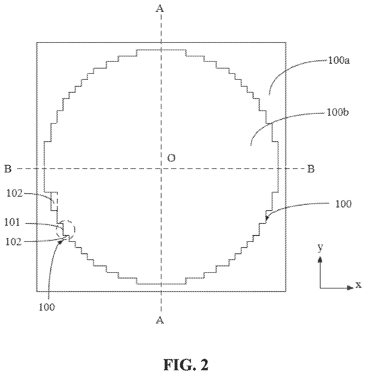
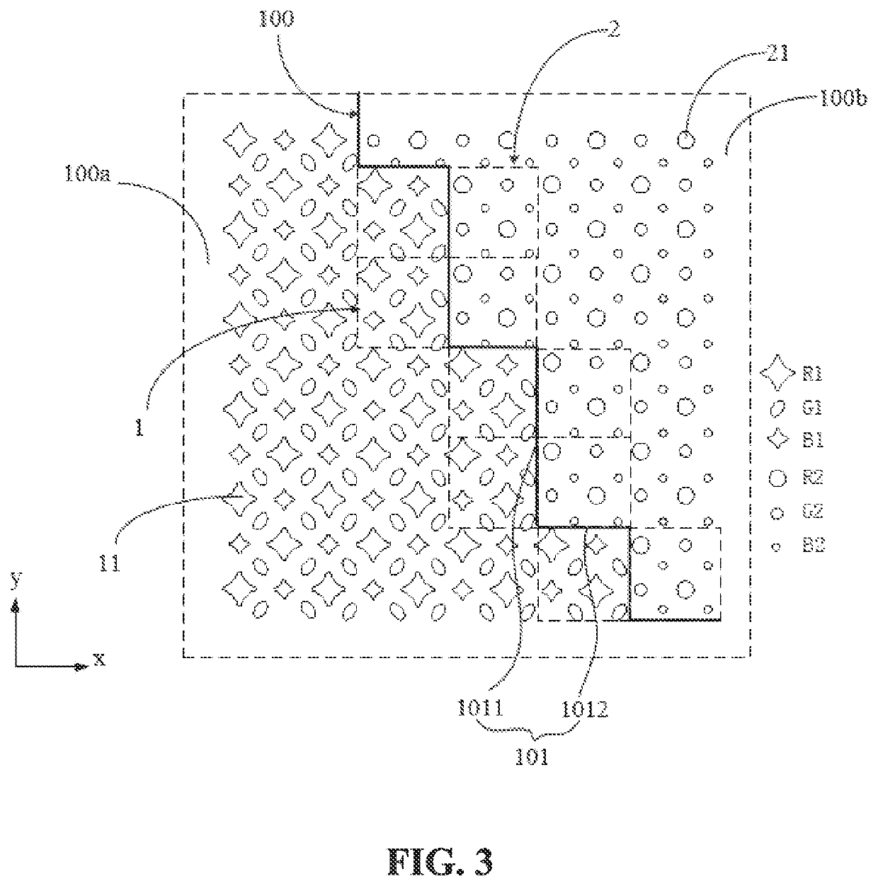
The present patent discloses a display panel and display device with a bend line boundary between the main display region and sub display region. This boundary includes multiple bending units, each corresponding to a pixel repeating unit in the sub display region. This results in complete pixel repeating units at the bend line boundary, reducing differences in display between the sub display region and its edge, and improving visual performance.

Problems solved by technology

In this way, a transmission rate of the panel will be relatively high, but user's display experience is not good, and a full-screen display cannot be achieved.

Method used


Image

  • Display panel and display device
  • Display panel and display device
  • Display panel and display device

Examples


Embodiment Construction

[0043]The description of the following embodiments refers to the attached drawings to illustrate specific embodiments that the present disclosure can be implemented. Direction terms mentioned in the present disclosure, such as top, bottom, front, back, left, right, inside, outside, side, etc., only refer to the directions of the attached drawings. Therefore, the directional terms are used to explain and understand the present disclosure, not to limit the present disclosure. In the drawings, units with similar structures are indicated by the same reference numerals.

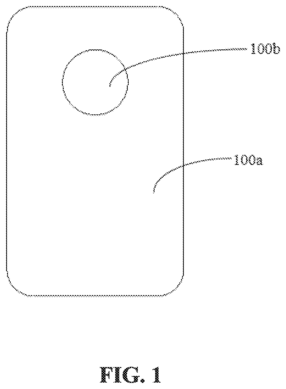
[0044]Please refer to FIG. 1, which is a plan view of a display panel of an embodiment of the present disclosure. The display panel is an active matrix organic light emitting diode display panel. The display panel includes a main display region 100a and at least one sub display region 100b. The main display region 100a is a region mainly configured to display images. The sub display region 100b can be configured to display...


PUM


Abstract

A display panel and a display device are provided. The display panel includes a main display region, a sub display region, a plurality of first pixel repeating units disposed in the main display region, and a plurality of second pixel repeating units disposed in the sub display region. A bend line boundary is firmed between the main display region and the sub display region. The bend line boundary includes a plurality of bending units. Each bending unit corresponds to at least one second pixel repeating unit, so that the pixel repeating units of the sub display region are consistent with the pixel repeating units at its edge, and a display difference is reduced.

Description

FIELD OF DISCLOSURE[0001]The present disclosure relates to the field of display technologies, and in particular to a display panel and a display device.BACKGROUND[0002]Full-screen displays bring people a brand-new visual experience and sensory impact due to its extremely high screen-to-body ratio, and have become a goal of display panel manufacturers.[0003]At present, a common design of an under-screen camera is to form a hole in a camera area of a display panel. No image is displayed in a camera light-transmitting area. In this way, a transmission rate of the panel will be relatively high, but user's display experience is not good, and a full-screen display cannot be achieved. In another way, a sub display region is formed on a display panel, and an under-screen camera is disposed correspondingly to the sub display region. The sub display region can adjust a light transmittance and be provided with display pixels, so that the camera can take pictures and the sub display region can ...

Claims


Application Information

Patent Timeline
IPC IPC(8): H01L27/32
CPCH01L27/3218H01L27/3244H01L27/3216G09F9/30G09F9/302G09F9/33H10K59/352H10K59/353H10K59/65H10K59/12
Inventor YI, CHUJUNCHEN, TAO
Owner WUHAN CHINA STAR OPTOELECTRONICS SEMICON DISPLAY TECH CO LTD
Learn More