
Display panel and display device

A display panel and display area technology, which is applied to instruments, semiconductor devices, computing, etc., can solve the problems of uneven display of display devices, white lumps in photosensitive areas, affecting the display effect of display devices, etc., so as to improve the display effect and reduce the display noise. Average, reduce the effect of display difference

Pending Publication Date: 2021-11-12
WUHAN TIANMA MICRO ELECTRONICS CO LTD
View PDF0 Cites 0 Cited by
  • Summary
  • Abstract
  • Description
  • Claims
  • Application Information

AI Technical Summary

Problems solved by technology

However, in the process of using display devices such as mobile phones and tablets, users find that there is a problem of uneven display during the use of the display device, resulting in white spots in the photosensitive area, which affects the display effect of the display device

Method used


Image

  • Display panel and display device
  • Display panel and display device
  • Display panel and display device

Examples


Embodiment Construction

[0031] The characteristics and exemplary embodiments of various aspects of the application will be described in detail below. In order to make the purpose, technical solutions and advantages of the application clearer, the application will be further described in detail below in conjunction with the accompanying drawings and specific embodiments. It should be understood that the specific embodiments described here are only configured to explain the application, not to limit the application. It will be apparent to one skilled in the art that the present application may be practiced without some of these specific details. The following description of the embodiments is only to provide a better understanding of the present application by showing examples of the present application.

[0032] It should be noted that in this article, relational terms such as first and second are only used to distinguish one entity or operation from another entity or operation, and do not necessarily...


PUM

PropertyMeasurementUnit
thicknessaaaaaaaaaa
thicknessaaaaaaaaaa
thicknessaaaaaaaaaa

Abstract

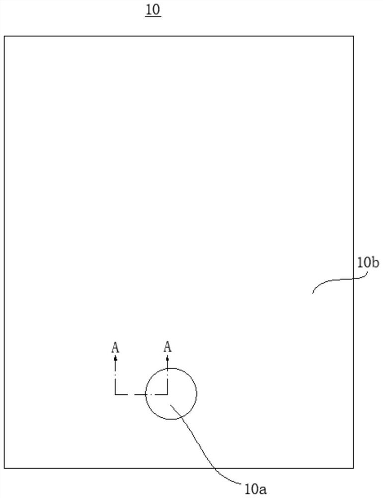
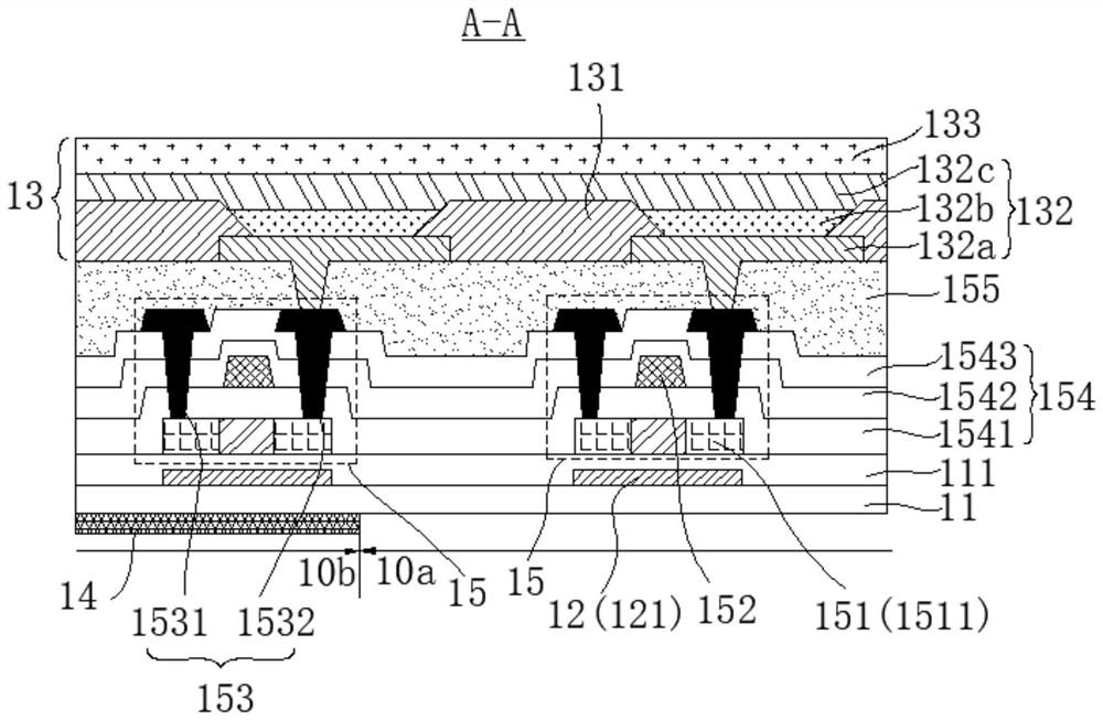
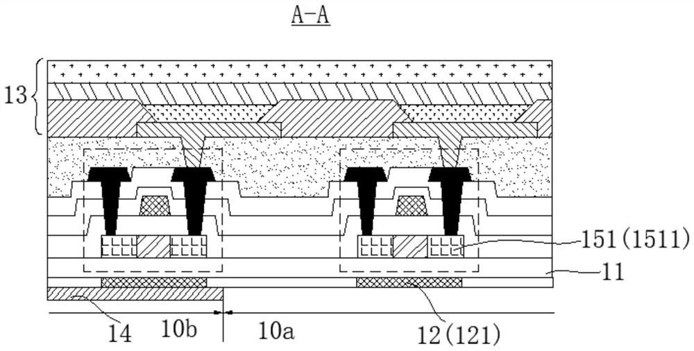
The invention provides a display panel and a display device, and the display panel comprises a photosensitive area, a substrate, a light-emitting layer, and a light blocking layer. A semiconductor layer is arranged on one side of the substrate and comprises a plurality of semiconductor elements, and the semiconductor elements comprise first semiconductor elements located in the photosensitive area. The light-emitting layer is located on the side, away from the substrate, of the semiconductor layer, the light blocking layer is located on the side, away from the light-emitting layer, of the semiconductor layer, the light blocking layer comprises a plurality of first light blocking parts arranged at intervals, and the first light blocking parts correspond to the first semiconductor elements. The orthographic projection of the first light blocking part on the plane where the substrate is located is at least partially overlapped with the orthographic projection of the first semiconductor element on the plane where the substrate is located. According to the display panel, the first light blocking part is arranged on the side, away from the light-emitting layer, of the first semiconductor element, the intensity of light irradiated to the first semiconductor element is effectively reduced, the display difference of the display panel is reduced, and the display effect of the display panel is improved.

Description

technical field [0001] The present application relates to the field of display technology, in particular to a display panel and a display device. Background technique [0002] At present, when FOD (Finger on Dispaly) technology is applied to the display panel, it can not only realize the front touch display panel, but also realize the safe unlocking function of the display panel, which not only facilitates the operation of the user, but also The appearance of the display panel is improved, so it is widely used in display devices such as mobile phones and tablets. [0003] Usually, a photosensitive area is provided on the display panel, and a photosensitive element is arranged in the photosensitive area, and fingerprint recognition is performed through the photosensitive element to realize unlocking of the display device. After the screen is unlocked, the photosensitive area can perform normal touch operations. However, in the process of using display devices such as mobile ...

Claims


Application Information

Patent Timeline
Patent Type & Authority Applications(China)
IPC IPC(8): H01L27/32G06K9/00G02F1/1333
CPCG02F1/13338H10K59/60H10K59/40H10K59/12
Inventor 凡艳云刘芬熊志勇陈开聪
Owner WUHAN TIANMA MICRO ELECTRONICS CO LTD
Learn More