Bottle assembly

a technology for bottles and containers, applied in the direction of pliable tubular containers, transportation and packaging, cooking vessels, etc., can solve the problems of cumbersome dispensing operation, unwieldy, and difficult storag

Inactive Publication Date: 2000-01-11
ALBERTS SCOTT
View PDF5 Cites 6 Cited by
  • Summary
  • Abstract
  • Description
  • Claims
  • Application Information

AI Technical Summary

Problems solved by technology

While this type of dispensing container is adequate for the purpose, it exhibits a number of drawbacks.
For example, the prior art containers of this type are generally quite tall, are awkward to store and tend to

Method used


Image

  • Bottle assembly
  • Bottle assembly
  • Bottle assembly

Examples


Embodiment Construction

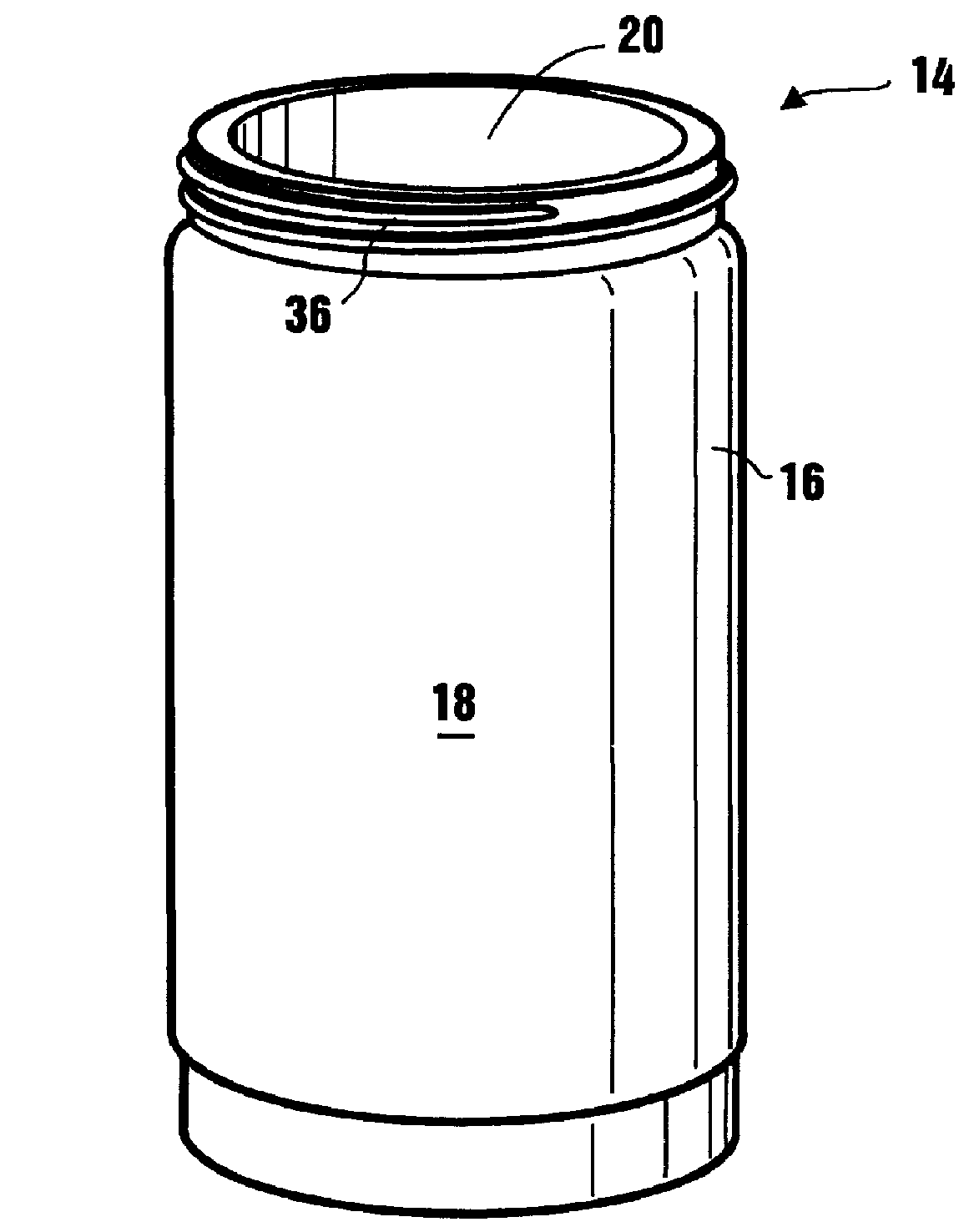
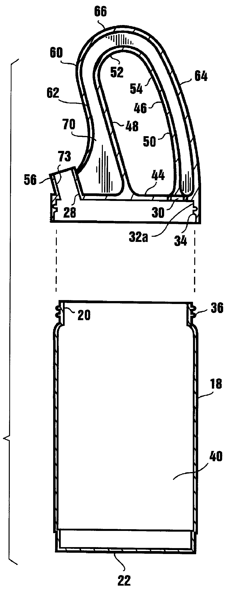
Referring to the drawings and particularly to FIGS. 1 and 3, one form of the bottle assembly of the present invention is there illustrated and generally designated by the numeral 14. In this form of the invention the bottle assembly comprises a container 16, for containing the beverage to be dispensed. Container 16 includes a generally cylindrically shaped wall 18 which defines an open top 20. The bottom of container 16 is closed by a bottom closure wall 22. (FIG. 3)

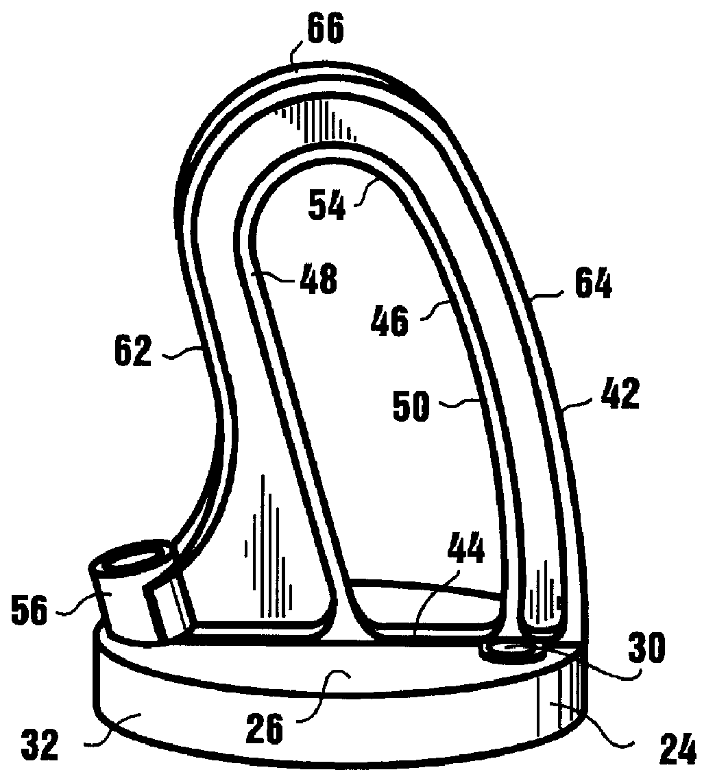
Closure means is provided for closing the open top of the beverage container and here comprises a closure member 24 which is generally cap like in configuration. Closure member 24 includes a top wall 26 having first and second openings 28 and 30 formed therein. (See also FIG. 2) Extending downwardly from top wall 26 is a generally cylindrically shaped flange 32 which circumscribes top wall 26 in the manner shown in FIG. 1. Flange 32 has an inner wall 32a (FIG. 3), which is provided with threads 34 which are mutable with ...


PUM


Abstract

A bottle assembly for use in the convenient storage and dispensing of beverages of the character used in restaurants and bars to make mixed drinks. The bottle assembly is compact, easy to use, and permits the smooth dispensing of the beverage contained within the container portion of the assembly in a rapid and efficient manner. Additionally, the bottle assembly embodies a unique handle design for gripping by the user which enables beverages to be poured from the container in an ergonomically sound manner so that undue stresses on the hand and wrist of the user are substantially avoided.

Description

1. Field of the InventionThe present invention relates generally to fluid dispensing containers. More particularly, the invention concerns a uniquely designed beverage dispensing container which is ideally suited for use by bartenders in dispensing beverages used in mixing mixed drinks.2. Discussion of the Prior ArtVarious types of container tops have been suggested in the past to improve the pouring of liquid contents of the container. One type of container top frequently used by bartenders comprises a top having an upwardly extending, generally conically shaped portion which has at its upper extremity a pour opening for dispensing the liquid contained within the container to which the top is interconnected. While this type of dispensing container is adequate for the purpose, it exhibits a number of drawbacks. For example, the prior art containers of this type are generally quite tall, are awkward to store and tend to be somewhat unwieldable during use. Not only is the dispensing o...

Claims


Application Information

Patent Timeline
IPC IPC(8): A47J43/27A47J43/00A47J36/14A47J36/00
CPCA47J36/14A47J43/27
Inventor ALBERTS, SCOTT
Owner ALBERTS SCOTT
Why Eureka
Try Eureka