Method of molding composite insulator and metal molding apparatus used for this molding method

a metal molding and composite insulator technology, applied in the direction of manufacturing tools, food shaping, drawing profiling tools, etc., can solve the problems of insufficient connection of respective members, so-called scorching, and insufficient curing time, so as to achieve excellent products without adversely affecting products.

Inactive Publication Date: 2000-02-01
NGK INSULATORS LTD
View PDF10 Cites 17 Cited by
  • Summary
  • Abstract
  • Description
  • Claims
  • Application Information

AI Technical Summary

Benefits of technology

In the present invention, an additional heating means is arranged at a portion in the metal mold near or faced to the metal fittings, and the portion in the metal mold near or faced to the metal fittings is further heated in addition to a normal metal mold heating for the curing operation. Therefore, it is possible to make a temperature increase of the overcoat portion forming materials near the metal fittings, which in lower than that of the other portion in a conventional one, equal to that of the other portion. In this case, a molding and curing operation is finished in a short time without adversely affecting a product and an excellent product can be obtained.

Problems solved by technology

If such an insufficient curing portion exists, there is a case that respective members are not connected sufficiently.
Therefore, it was found that such a total curing time increase was little for one molding operation but there was a large problem on the curing time if a large number of polymer insulators are molded in a large scale manufacturing.
However, in this case, it was found that a so-called scorch, in which a rough portion was generated on a surface of the product, occurred.
However, in this case, it was found that the core member 53 was softened and a handling of the core member 53 before the molding operation became very difficult.

Method used


Image

  • Method of molding composite insulator and metal molding apparatus used for this molding method
  • Method of molding composite insulator and metal molding apparatus used for this molding method
  • Method of molding composite insulator and metal molding apparatus used for this molding method

Examples


Embodiment Construction

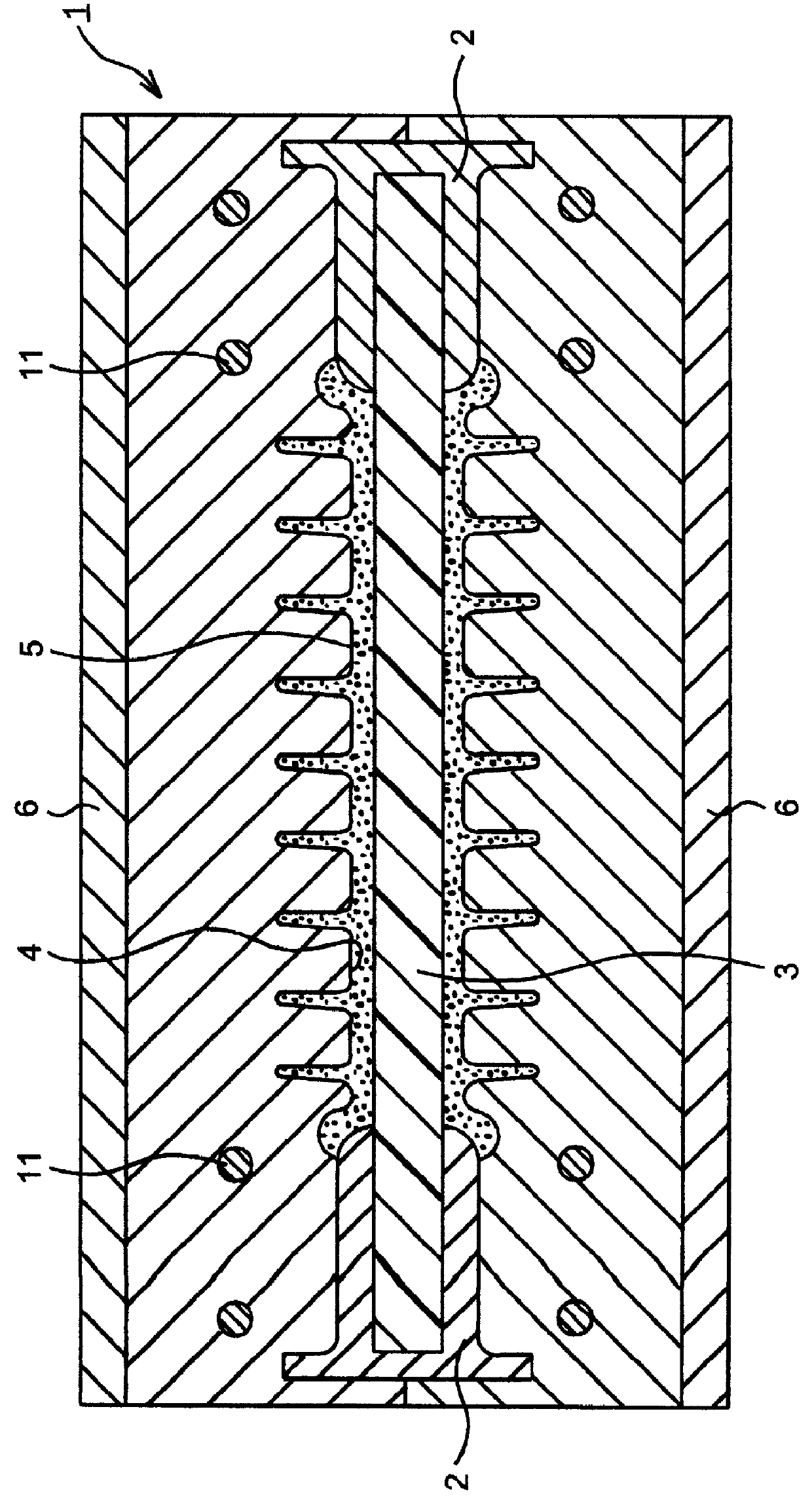
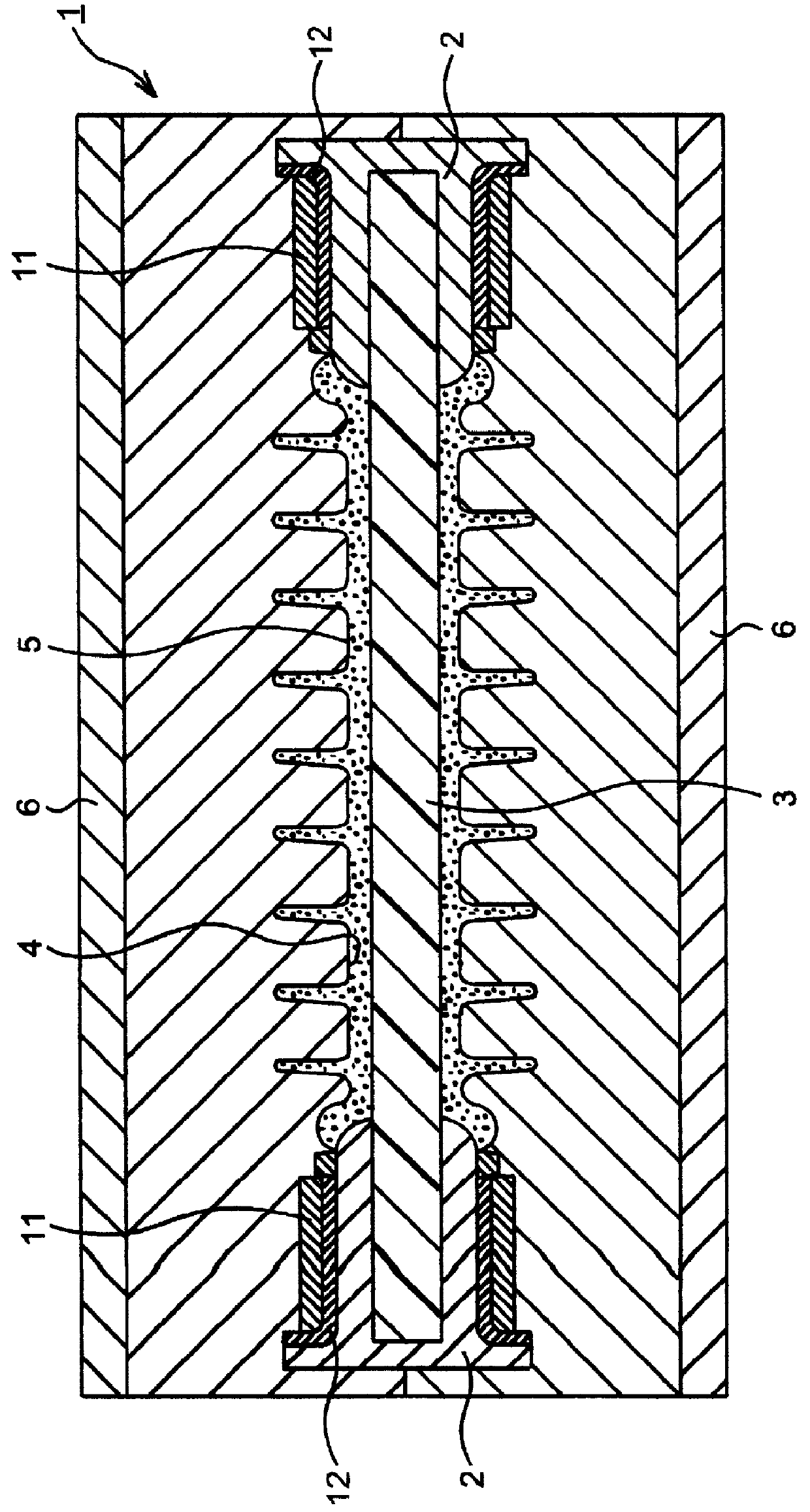
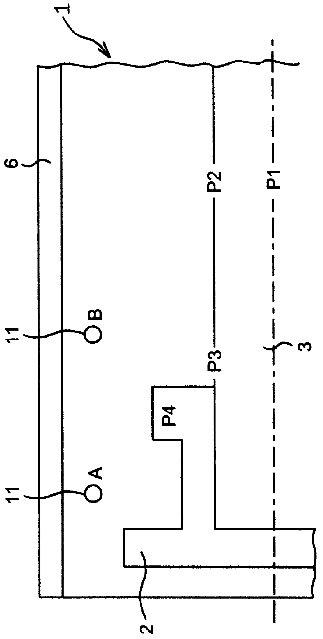
As shown in FIG. 3, the metal mold 1 according to the invention in which the additional heaters 11 were arranged at positions A and B therein near the flange metal fitting 2 and a metal old according to a comparative example in which no additional heater was arranged were prepared. In the prepared metal molds according to the invention and the comparative example, thermocouples were embedded in the core member 3 at positions P1-P3, and also a thermocouple was embedded in the flange metal fitting 2 at a position P4. Then, temperatures at the positions P1-P4 were measured when the overcoat portion forming materials made of silicon rubber was heated. In all the cases, the molding operation was started at a metal mold temperature of 170.degree. C., and, in the case that the additional heater was used, setting temperatures of the additional heaters were 180.degree. C. and 175.degree. C. Moreover, in all the cases, the core member 3 made of FRP and the flange metal fitting 2 were prelimin...


PUM

PropertyMeasurementUnit
temperatureaaaaaaaaaa
temperaturesaaaaaaaaaa

Abstract

A method of molding a composite insulator having a core member and an overcoat portion arranged on an outer surface of the core member, in which a core member having metal fittings at both ends thereof is set in a metal mold for molding the composite insulator, overcoat portion forming materials are filled in a cavity for molding said overcoat portion formed around the core member, and then the overcoat portion forming materials are cured by heat, is disclosed. The improved method includes a step of making a temperature increase of the overcoat portion forming materials near the metal fittings equal to that of the other portion, when the overcoat portion forming materials are cured by heat, by utilizing an additional heating means.

Description

1. Field of the InventionThe present invention relates to a method of molding a composite insulator utilizing a metal mold and a metal molding apparatus used for this molding method.In the present invention, "composite insulator" has a core member made of fiber reinforced plastics and an overcoat portion made of insulation polymer materials arranged on an outer surface of the core member, and it means a wide concept including not only polymer insulator in which the core member is formed by an FRP solid member but also polymer hollow insulator or hollow SP insulator in which the core member is formed by an FRP cylindrical member. Moreover, the overcoat portion generally has a cylindrical sheath portion arranged on an outer surface of the core member and a plurality of sheds arranged on an outer surface of the sheath portion with a predetermined interval. Further, as insulation polymer materials, silicone rubber, ethylene-propylene copolymer (RPM), ethylene-propylene-diene copolymer (...

Claims


Application Information

Patent Timeline
Patent Type & Authority Patents(United States)
IPC IPC(8): B29C33/02B29C43/18H01B19/00B29C35/02B29C39/26B29C39/10B29C39/38B29L31/34
CPCB29C33/02B29C43/18H01B19/00B29C2035/0211B29L2031/3412
Inventor KASHIWAGI, HIROSHI
Owner NGK INSULATORS LTD
Why Eureka
Try Eureka