Water-impact release mechanism

Inactive Publication Date: 2000-02-15
THE UNITED STATES OF AMERICA AS REPRESENTED BY THE SECRETARY OF THE NAVY
View PDF5 Cites 14 Cited by
  • Summary
  • Abstract
  • Description
  • Claims
  • Application Information

AI Technical Summary

Problems solved by technology

Accordingly, if the inertial force does not overcome the drag force sufficiently, the relea

Method used


Image

  • Water-impact release mechanism
  • Water-impact release mechanism
  • Water-impact release mechanism

Examples


Embodiment Construction

)

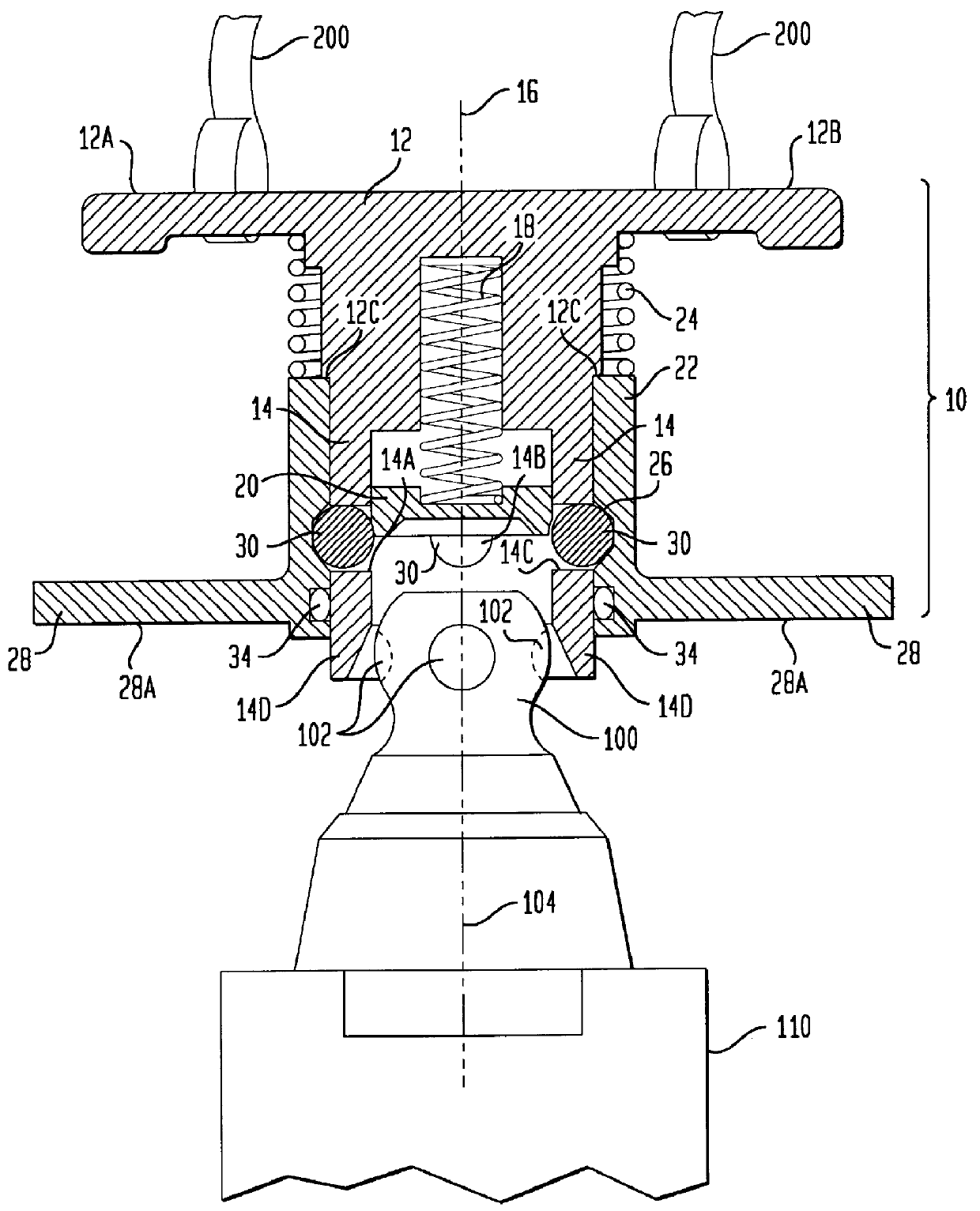
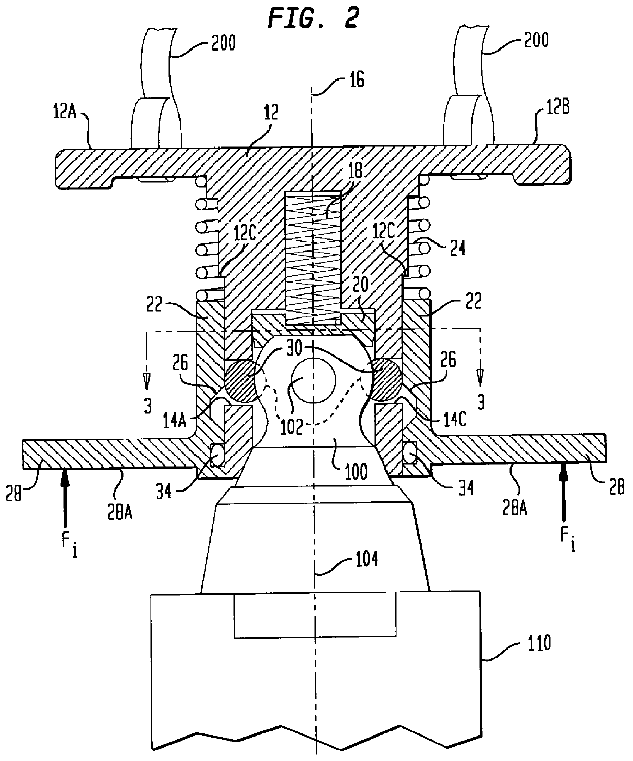
Referring now to the drawings, simultaneous reference will be made to FIGS. 1, 2 and 3 in order to explain the water-impact release mechanism of the present invention which is referenced generally by numeral 10 in FIGS. 1 and 2. In the illustrated embodiment, a dimpled tail nut or hitching ball 100 is the device to be engaged and released by release mechanism 10. Hitching ball 100 is typically attached to the aft end of a payload 110 (e.g., a torpedo) that is to be deployed in air over a body of water into which payload 110 is to fall. By way of example, hitching ball 100 has a plurality of spherical dimples 102 distributed about the periphery thereof in a plane perpendicular to the longitudinal axis 104 of hitching ball 100 and payload 110. This design of hitching ball 100 is one commonly used by the Navy.

Release mechanism 10 has a hub structure 12 which, for the illustrated embodiment, has a plurality of spokes, (only two spokes 12A and 12B are shown for sake of clarity,) extendi...


PUM


Abstract

A water-impact release mechanism has a hub with a first sleeve coupled thereto. The first sleeve has a plurality of circumferentially distributed holes therein. A spring assembly, coupled to the hub, extends into the first sleeve. In a relaxed state, the spring assembly obstructs the holes while, in a compressed state, the spring assembly does not obstruct the holes. A second sleeve, concentric with the first sleeve, is elastically coupled to the hub and biased away therefrom. The second sleeve has an inwardly-facing annular groove. A ball resides in each of the holes and is large enough to extend beyond the confines of its hole. When the bias of the second sleeve is overcome, the annular groove aligns with the holes in the first sleeve thereby allowing the radial outward movement of the balls. A plate, coupled to the second sleeve, extends radially outward therefrom to define a water-impact surface. Water-impact forces impinging on the plate cause the bias of the second sleeve to be overcome such that the second sleeve abuts the hub.

Description

(1) Field of the InventionThe present invention relates generally to release mechanisms, and more particularly to a water-impact release mechanism used to couple a deceleration device, e.g., a parachute, to the aft end of an air-deployed device, e.g., a torpedo.(2) Description of the Prior ArtIn some Navy applications, torpedoes having air stabilizing devices (e.g., a parachute) are launched from an aerial platform (e.g., helicopter, airplane, etc.). The use of an air stabilizing device reduces the velocity upon water impact in order to prevent damage to the torpedo's structure or control systems. The air stabilizing device is generally coupled to the aft end of the torpedo by means of a release mechanism that causes the air stabilizing device to separate from the torpedo when it strikes the water. More specifically, a tail nut (i.e., similar to a hitching ball) generally extends from the aft end of the torpedo for cooperation with the release mechanism.A variety of release mechanis...

Claims


Application Information

Patent Timeline
IPC IPC(8): B64D17/00B64D17/38
CPCB64D17/383
Inventor GODFREY, DANIEL M.BERLAM, GARY R.
Owner THE UNITED STATES OF AMERICA AS REPRESENTED BY THE SECRETARY OF THE NAVY
Why Eureka
Try Eureka