High speed trimming shear

a cutting shear and high-speed technology, applied in the field of high-speed cutting shears, can solve the problems of difficult coordination and control precisely, mechanical complexity, and inability to meet,

Inactive Publication Date: 2000-03-07
MORGAN CONSTR CO
View PDF20 Cites 16 Cited by
  • Summary
  • Abstract
  • Description
  • Claims
  • Application Information

AI Technical Summary

Problems solved by technology

The shears of the prior art have various shortcomings which inhibit their ability to meet these challenges.
These arrangements are mechanically complex, difficult to coordinate and control precisely, and are thus not suitable for very high speed operations

Method used


Image

  • High speed trimming shear
  • High speed trimming shear
  • High speed trimming shear

Examples


Embodiment Construction

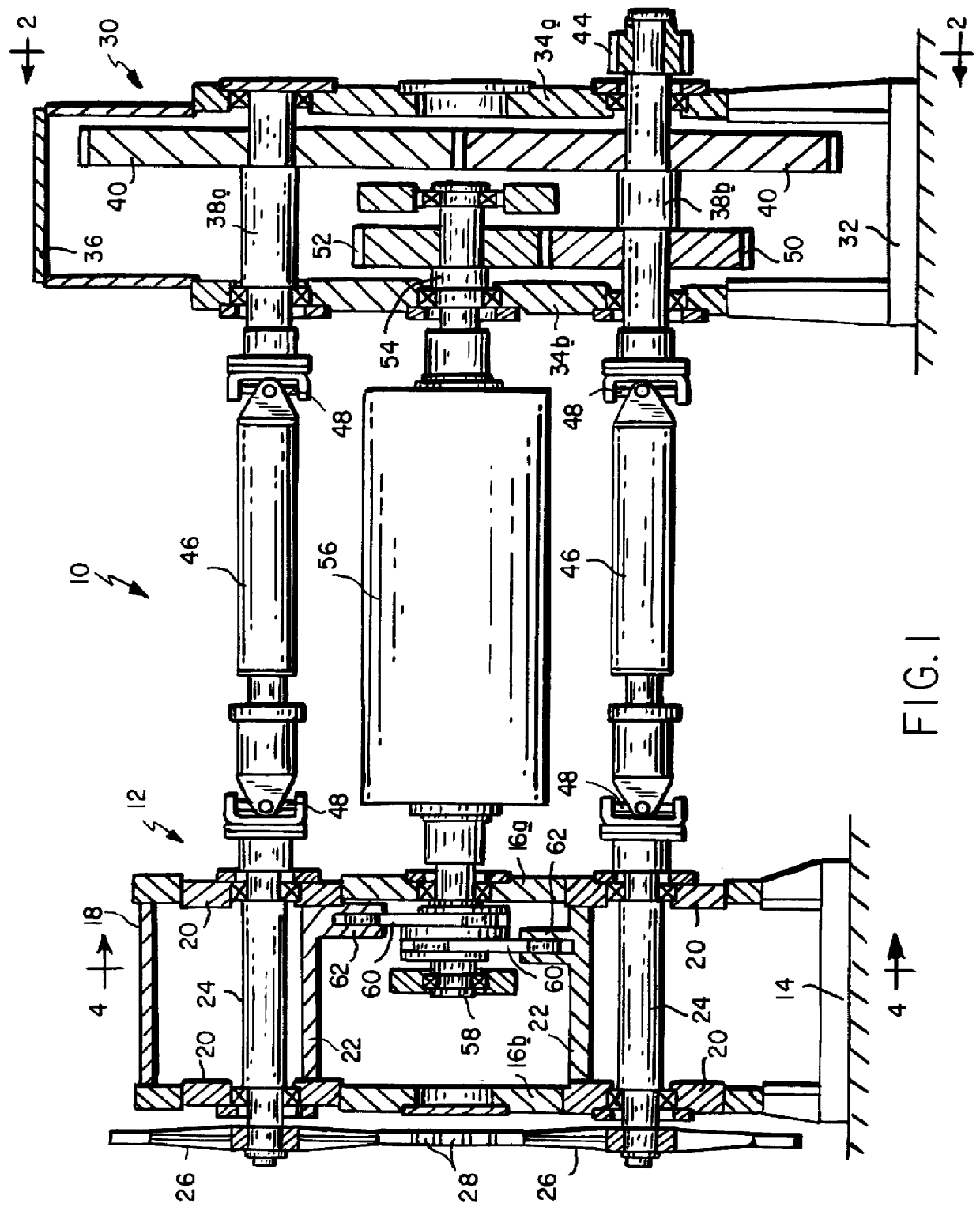
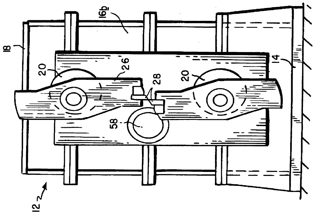
With reference to the drawings, a shear in accordance with the present invention is generally depicted at 10. A first housing 12 includes a base 14, end plates 16a, 16b and a cover 18. Axially aligned pairs of eccentrically bored sleeves 20 are supported in the housing end plates 16a, 16b for rotation about parallel first axes. The sleeves 20 of each pair are joined by yokes 22. Carrier shafts 24 are supported in the bores of the sleeves 20 for rotation about second axes parallel to the rotational sleeve axes. The carrier shafts have blade holders 26 with cutting blades 28 mounted thereon.

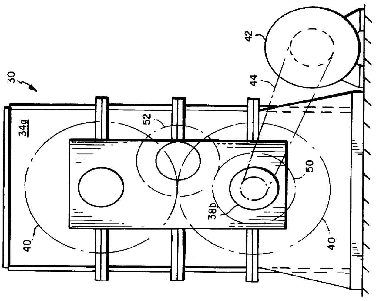
A second housing 30 also includes a base 32, end plates 34a, 34b and a cover 36. Drive shafts 38a, 38b are supported in the housing 30 between the end plates 34a, 34b for rotation about fixed parallel axes. The drive shafts 38a, 38b carry intermeshed gears 40, with the lower drive shaft 38b being driven by a motor 42 via a pulley 44 or the like. The drive shafts 38a, 38b are connected to the carrie...


PUM

PropertyMeasurementUnit
Speedaaaaaaaaaa
Distanceaaaaaaaaaa

Abstract

A high speed rod trimming shear includes a pair of eccentrically bored sleeves mounted for rotation about parallel first axes. Carrier shafts are supported in the bores of the eccentric sleeves for rotation about second axes parallel to the first axes and located on opposite sides of the rod path. The carrier shafts have blade holders with attached cutting blades. A primary drive rotates the carrier shafts continuously, and an adjustment mechanism rotatably oscillates the eccentric sleeves to adjust the distance between the carrier shafts between a first setting at which the cutting blades rotate out of contact with the rod, and a second setting at which the cutting blades coact during rotation to sever the product.

Description

1. Field of the InventionThis invention relates to high speed shears of the type employed to trim the front and tail ends of hot rolled steel rods and other like products moving at speeds exceeding 100 m / sec.2. Description of the Prior ArtIn order to reliably trim both the front and tail ends of rods traveling at the high delivery speeds of modem rolling mills, which are now reaching 120 m / sec., the shear blades must rotate continuously at speeds synchronized with mill delivery speeds, and they must be arranged for precise coordinated movement into and out of cutting positions during extremely brief time intervals of less than about 6 milliseconds. The shears of the prior art have various shortcomings which inhibit their ability to meet these challenges.For example, as disclosed in U.S. Pat. No. 2,451,948 (Hawthorne); U.S. Pat. No. 3,057,239 (Teplitz); U.S. Pat. No. 4,027,565 (Elsner et al.); and U.S. Pat. No. 4,640,164 (Pavlov), various schemes have been developed to effect radial ...

Claims


Application Information

Patent Timeline
IPC IPC(8): B23D36/00B23D25/12B23D25/00
CPCB23D25/12B23D36/0083Y10T83/4708Y10T83/4711Y10T83/483Y10T83/4833Y10T83/4836Y10T83/7843Y10T83/7855Y10T83/7872
Inventor PUCHOVSKY, MELICHER
Owner MORGAN CONSTR CO
Why Eureka
Try Eureka