Slotted hammermill hammer

a hammer and hammer mill technology, applied in the field of hammers, can solve the problems of periodic replacement, difficult to do, and substantial wear and stress of hammers during operation

Inactive Publication Date: 2000-04-04
DZ GRINDERS LLC
View PDF15 Cites 98 Cited by
  • Summary
  • Abstract
  • Description
  • Claims
  • Application Information

AI Technical Summary

Benefits of technology

These objects are achieved through the use of an slotted hammer assembly which is installed and used with a conventional hammermill rotor assembly formed of a rotor shaft and a plurality of alternating spacers and hammer rings between which the hammer assemblies can be interfitted and held in place by means of hammer rods.

Problems solved by technology

The problem is that the hammers undergo substantial wear and stress during operation.
However, even with the wear tip, hammers do occasionally, and in some cases routinely, break, and therefore must be periodically replaced.
If the broken hammer resides in the middle of the hammermill assembly, this may result in the withdrawal of the hammer rods past many rings to get at the broken hammer, resulting in the removal and reinstallation of a number of hammers just to replace the broken interior hammer.
This is not always an easy thing to do.
If any of the rings or the rod have deformed during operation, the rods may not be easy to remove.
At best, this is a time consuming and difficult job.

Method used


Image

  • Slotted hammermill hammer
  • Slotted hammermill hammer
  • Slotted hammermill hammer

Examples


Embodiment Construction

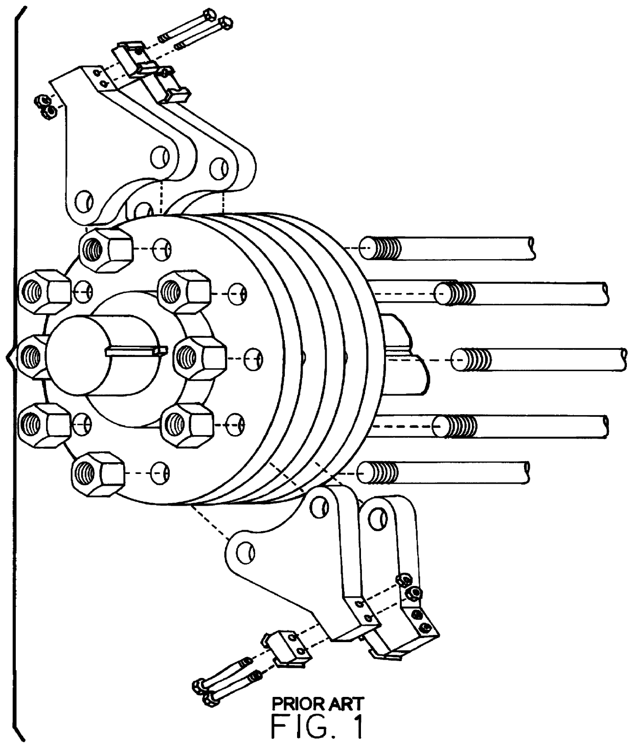
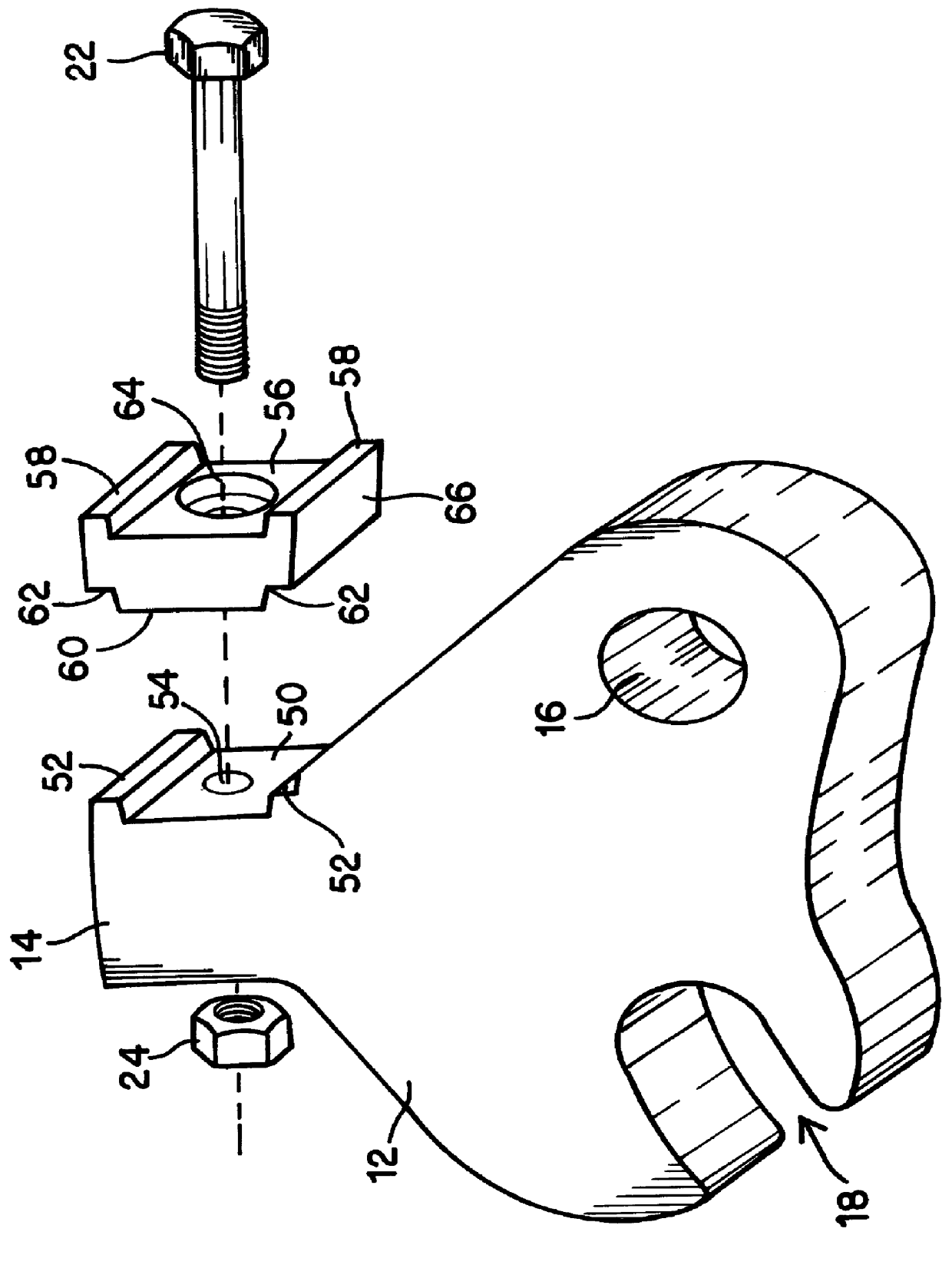
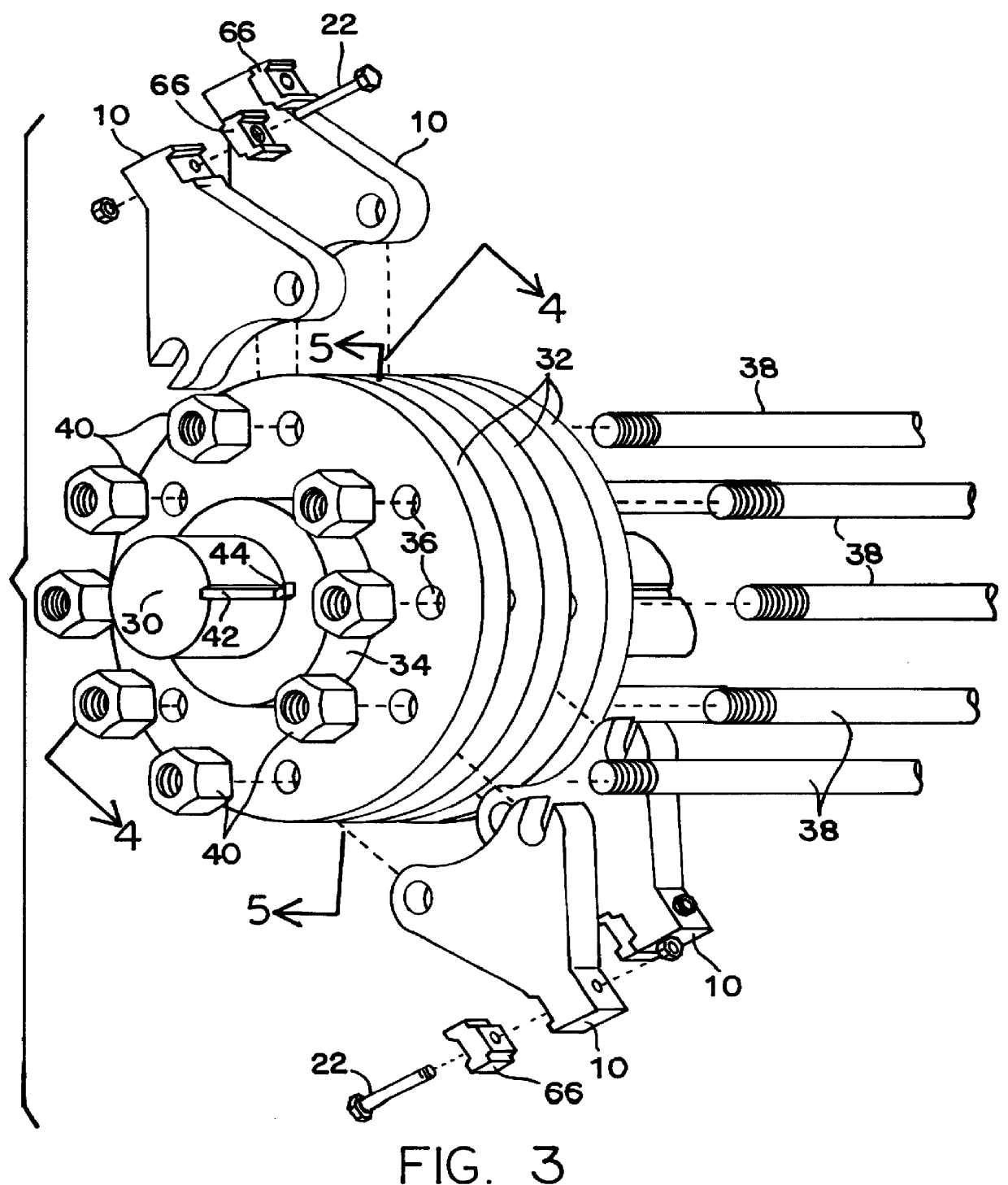
Referring to FIGS. 2 through 5, there is shown slotted hammer assembly 10 as it is installed and used in a conventional hammermill assembly rotor. Referring to FIGS. 3 and 4, there is shown a conventional hammermill rotor assembly formed of rotor shaft 30, onto which are attached a plurality of alternating spacers 34 and hammer rings 32. Spacers 34 are configured to separate hammer rings 32 to a desired width, such that hammer assemblies 10 can be interfitted between them and held in place by means of hammer rods 38. Spacers 34 and hammer rings 32 are attached to rotor 30 by means of a conventional key 44 interfitting within key ways 42. Not shown, but well known in the art are the end caps or bolts which are used to hold the entire rotor assembly together.

Each hammer ring 32 is provided with a radial array of ring rod holes 36, which are sized to receive and hold hammer rods 38. A plurality of hammer rod bolts 40 are provided to hold the rods firmly in place.

In the prior art, as is...


PUM


Abstract

An improved hammermill hammer is provided wherein the hammer body has an interlocking slot, to receive one of a pair of retaining rods, and a rod hole through which a second rod is interfitted to lock the hammer securely to the hammermill rotor.

Description

1. Technical FieldThis invention generally relates to hammers used in hammermill assemblies, and more particularly to a non-swinging hammer held in place by a pair of rods wherein the hammer body has an interlocking slot to receive one rod, and a rod hole through which a second rod is interfitted.2. BackgroundHammermills are used to grind a disparate and wide range of materials, including such things as tree stumps and slash from logging operations, land fill trash, to food products, such as grinding apples into mash in preparation for making apple cider. A typical hammermill assembly is formed of a rotor assembly to which a number of hammers are attached, a fixed cutter bar positioned alongside of the rotor assembly and in close relationship to where the hammers will pass by it, and beneath the rotor assembly a semi-circular screen. Material is dropped into the hammermill from the top, where it is impacted by the rotating hammers, and rotated around to a point where larger material...

Claims


Application Information

Patent Timeline
Patent Type & Authority Patents(United States)
IPC IPC(8): B02C13/28B02C13/00
CPCB02C13/2804
Inventor ZEHR, MELVIN A.
Owner DZ GRINDERS LLC
Why Eureka
Try Eureka