Method for mounting an element

a technology of mounting method and element, which is applied in the direction of casing/cabinet/drawer details, casing/cabinet/drawer, electrical apparatus, etc., can solve the problems of removing additional elements, using tools, and specialized tools

Inactive Publication Date: 2000-04-18
MICRON TECH INC
View PDF19 Cites 72 Cited by
  • Summary
  • Abstract
  • Description
  • Claims
  • Application Information

AI Technical Summary

Problems solved by technology

However, while mounting screws provide a firm fastening system, their use carries certain disadvantages.
First, they require the use of tools for removal and installation.
These tools are often very specialized due to cramped conditions inside the computer chassis.
Second, to access mounting screws, it is often necessary to remove additional elements.
Complicated disassembly is time consuming and can cause damage to other parts of the computer.
In the above-mentioned example, if adequate care is not taken, t

Method used


Image

  • Method for mounting an element
  • Method for mounting an element
  • Method for mounting an element

Examples


Embodiment Construction

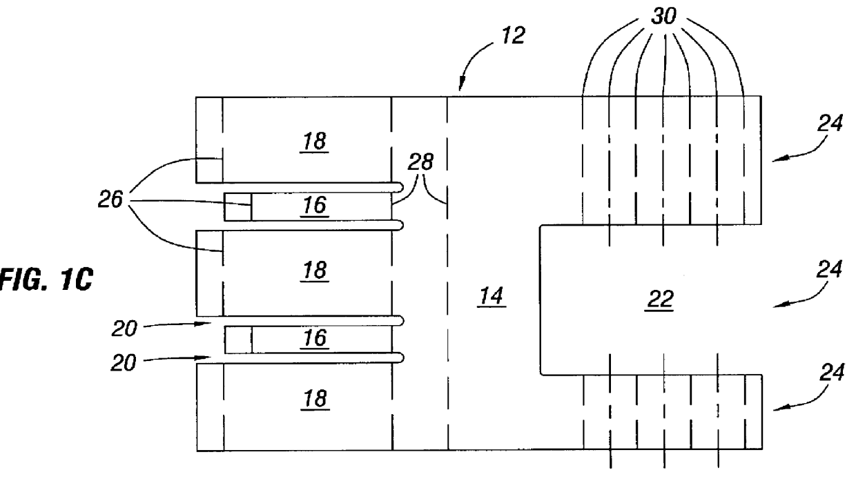
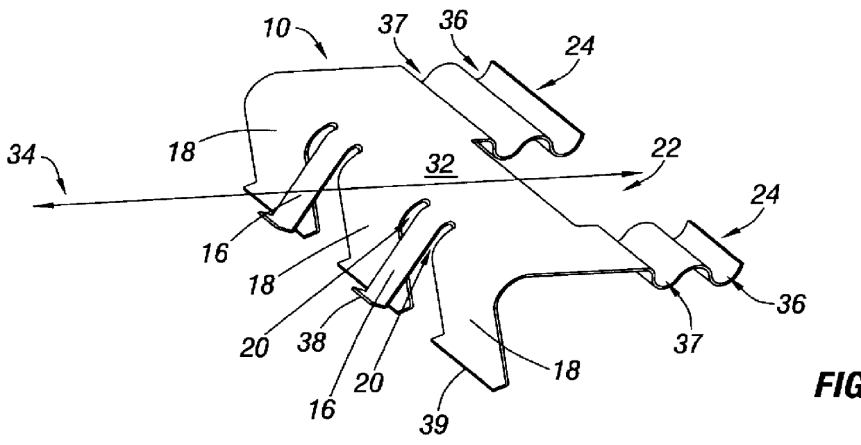
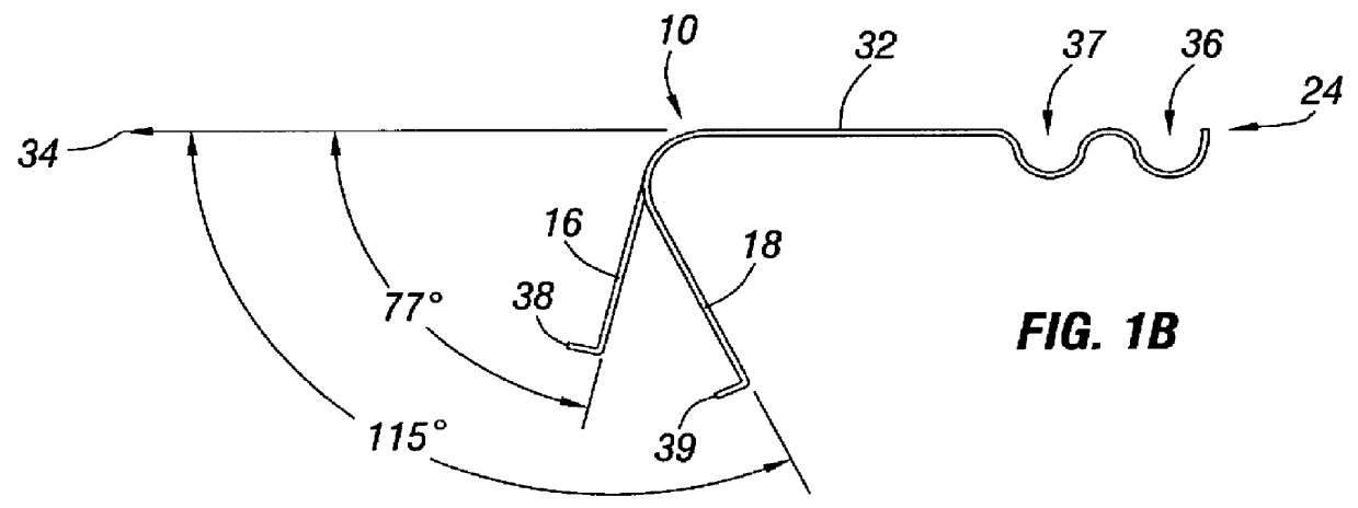
FIGS. 1A-1B are three dimensional and cross sectional views respectively of an element clip 10 in accord with one particular embodiment of the invention. FIG. 1C shows a flat metal piece 12 prior to a bending that is necessary to form the element clip 10 of FIGS. 1A-1B. The metal piece 12, in the embodiment of FIGS. 1C, comprises main body 14 having two narrow languets 16 disposed between three wider languets 18 on one side thereof. Small grooves 20 are cut between each pair of languets 16 and 18 to facilitate bending the languets 16 and 18 independently of one another. The metal piece 12 in the particular embodiment illustrated also has a slot 22 cut into its back side 24 which may be omitted in some embodiments. Though the slot 22 may be useful in certain embodiments, it is not essential to the function of the clip 10. Thus, slot 22 does not limit the scope of the present invention.

Broken lines 26, 28, and 30 in FIG. 1C indicate where the metal piece 12 is bent to form the element...


PUM


Abstract

The present invention provides a method for mounting an element on a chassis. The method comprises several steps. The element is stopped from sliding in at least one direction when the element is placed on the surface of the chassis. A clip is pivotably connected to the chassis. The clip pivots between first and second position holding the element in place in the second position. The clip is locked in the second position.

Description

1. Field of the InventionThe present invention relates generally to spring fasteners, and, more particularly, to a screwless mounting assembly for attaching a element to a computer chassis.2. Description of Related ArtIn constructing small machines such as computers, it is necessary to attach a variety of elements to a metal chassis frame. An important innovation in mini-computers has been the development of methods allowing owners to add or replace elements themselves. These innovations have enabled owners to inexpensively adapt and upgrade their machines. These additions and replacements have been facilitated by special attachment devices and methods.Heretofore, screw-type mounting arrangements have been widely used. However, while mounting screws provide a firm fastening system, their use carries certain disadvantages. First, they require the use of tools for removal and installation. These tools are often very specialized due to cramped conditions inside the computer chassis. Se...

Claims


Application Information

Patent Timeline
IPC IPC(8): G06F1/18H02B1/04H02B1/015H05K5/02
CPCG06F1/184G06F1/187H02B1/04H05K5/0204Y10T29/49876Y10T29/49947Y10T24/44923Y10T403/7176
Inventor BOE, CRAIG L.
Owner MICRON TECH INC
Why Eureka
Try Eureka