
Short span differential gear assembly

Inactive Publication Date: 2000-05-02
DANA AUTOMOTIVE SYST GRP LLC
View PDF12 Cites 42 Cited by
  • Summary
  • Abstract
  • Description
  • Claims
  • Application Information

AI Technical Summary

Problems solved by technology

Such prior art type differential gear assemblies however employ a great number of costly components and fasteners, and they require a large differential housing to protect the numerous components as well as requiring precise positioning of the side gears and fasteners within the differential case.

Method used


Image

  • Short span differential gear assembly
  • Short span differential gear assembly
  • Short span differential gear assembly

Examples


Embodiment Construction

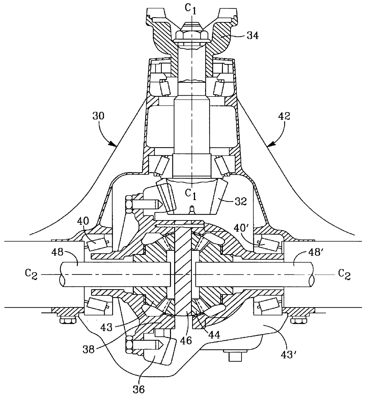
The prior art differential gear assembly 30 shown in FIG. 1 is of the type hereinbefore described requiring numerous components and a much larger housing to enclose them.

Assembly 30 transfers rotary torque from a pinion gear 32 driven by a rotary output shaft 34 of a change gear transmission to a ring gear 36 having teeth meshingly engaged with teeth on ring gear 36. Ring gear 36 is secured to a case 38 that is journaled for rotation relative housing 42 by means of bearings 40. As such, ring gear 36 and case 38 rotate coaxially about axle shaft 48 that has an side gear 43 secured to its inboard end by suitable means such as splines. It can thus readily be seen from FIG. 1 that prior art differential gear assemblies required precise and costly alignment between the ring gear and the differential housing.

Axle shaft 48 is spaced-apart from and substantially axially aligned with axle shaft 48' which has an side gear 43' secured to its inboard end in facing relationship to end gear 43. A...


PUM


Abstract

A ring gear (50) is provided between a pair of differential case halves (18, 18') integrally formed with teeth defining a pair of side gears (19, 19') that engage differential pinion gears (12, 12') mounted on a pinion shaft (17) to provide a motor vehicle differential gear assembly (100) having reduced components while enabling a limited slip capability controlled by regulating frictional resistance at a thrust surface interface.

Description

a) Field of the InventionThis invention relates generally to a vehicular differential gear case and gear assembly for transferring rotational torque from a rotary driver member such as a pinion gear driven by the output shaft of a change gear transmission to a pair of rotary driven members such as paired wheel axle shafts. More particularly, the invention relates to a ring gear and a differential gear assembly wherein the differential case and side gears are combined as a unitary body to provide a unique short span differential.b) Description of Related ArtConventional vehicle differential gear assemblies transfer rotational torque from a rotary driver member such as the output shaft of a change gear transmission to a pair of rotary driven members such as a pair of substantially axially aligned spaced-apart axle shafts journaled for rotation and having a wheel mounted on their respective outboard ends.Such prior art type differential gear assemblies however employ a great number of ...

Claims


Application Information

Patent Timeline
IPC IPC(8): F16H48/20F16H48/06F16H48/00F16H48/08F16H48/22F16H48/40F16H48/42
CPCF16H48/08F16H48/22F16H2048/423F16H48/40
Inventor FETT, GREGORY ALLEN
Owner DANA AUTOMOTIVE SYST GRP LLC
Features
  • Generate Ideas
  • Intellectual Property
  • Life Sciences
  • Materials
  • Tech Scout
  • Unparalleled Data Quality
  • Higher Quality Content
  • 60% Fewer Hallucinations
Learn More