Process and apparatus for operation of a slurry bubble column with application to the fischer-tropsch synthesis

a technology of slurry bubble column and fischer-tropsch synthesis, which is applied in the direction of chemistry apparatus and processes, organic chemistry, and preparation of oxygen-containing compounds, can solve the problem of limited catalyst productivity, and achieve the effect of stable operation

Inactive Publication Date: 2000-05-09
INST FR DU PETROLE +1
View PDF7 Cites 64 Cited by
  • Summary
  • Abstract
  • Description
  • Claims
  • Application Information

AI Technical Summary

Benefits of technology

The supply gas, which in the case of the Fischer-Tropsch synthesis is hydrogen and carbon monoxide, can be diluted with a certain quantity of another gas, i.e., normally less than about 30% by volume, preferably less than about 20% by volume, in particular nitrogen, methane or CO.sub.2. The supply gas is normally introduced into the bottom of the reactor and bubbles through it to the top of the reactor. The use of higher levels of diluting gas not only limits the maximum quantity of products formed per total volume of gas guided through the reactor, but also necessitates expensive separation stages to eliminate the diluent from the reactants of importance. The flow rate of the supply gas is normally as high as possible, while avoiding foam formation which occurs when the gas bubbles are not released from the liquid. This results in stable operation when the gas contained in the suspension does not increase with time or only increases slowly. Foam formation occurs when the residence time of the gas increases with time. The gas charge can be defined as the fraction of gas in the three phase suspension mixture. Appropriate velocities for the gas are those which entrain suspension of the particles in the liquid medium and are normally more than about 1 cm / second.

Problems solved by technology

However, this reactor technology has a major disadvantage which is known to the skilled person: the productivity of the catalyst is limited, in particular when the diameter of the reactor is increased or the linear velocity of the gases is increased.

Method used


Image

  • Process and apparatus for operation of a slurry bubble column with application to the fischer-tropsch synthesis
  • Process and apparatus for operation of a slurry bubble column with application to the fischer-tropsch synthesis
  • Process and apparatus for operation of a slurry bubble column with application to the fischer-tropsch synthesis

Examples


example 2

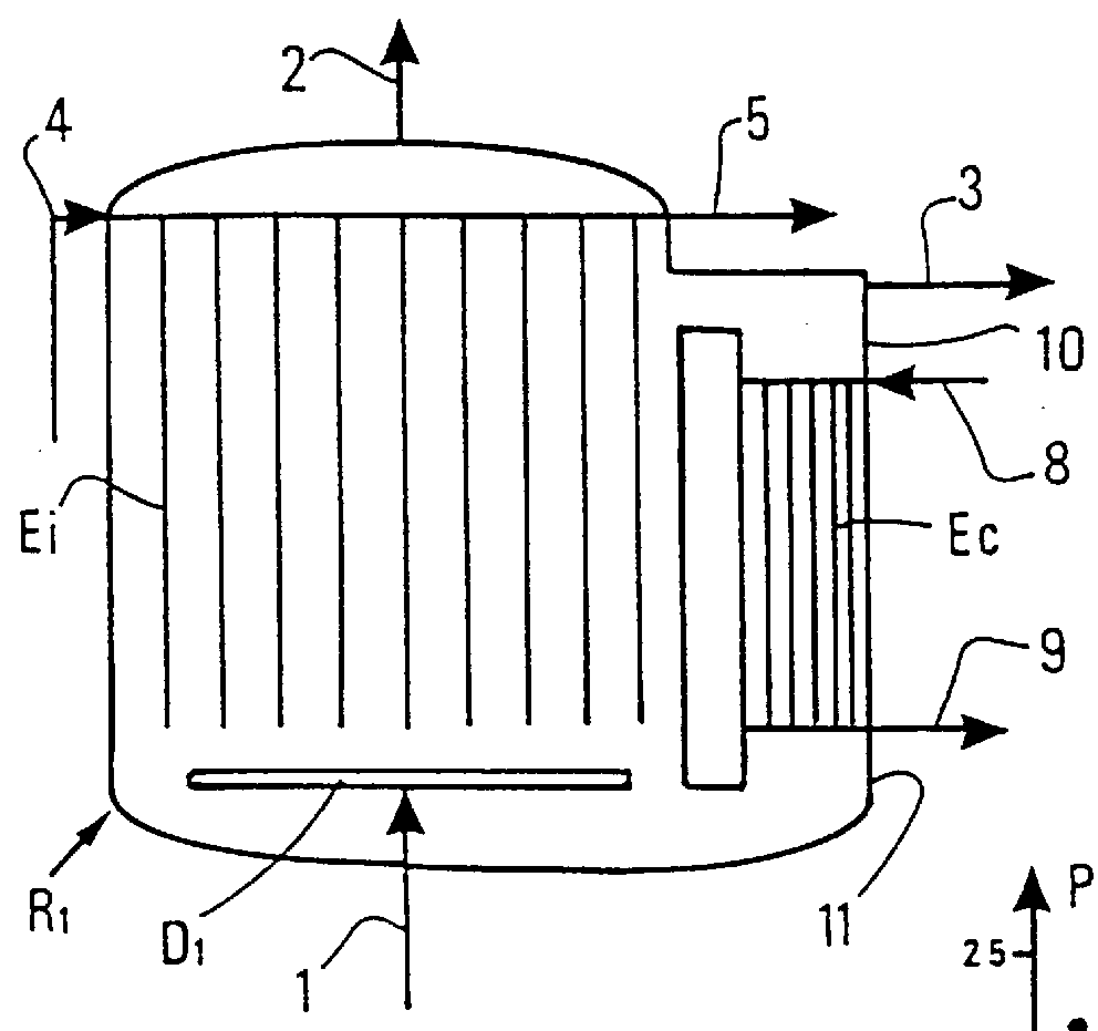
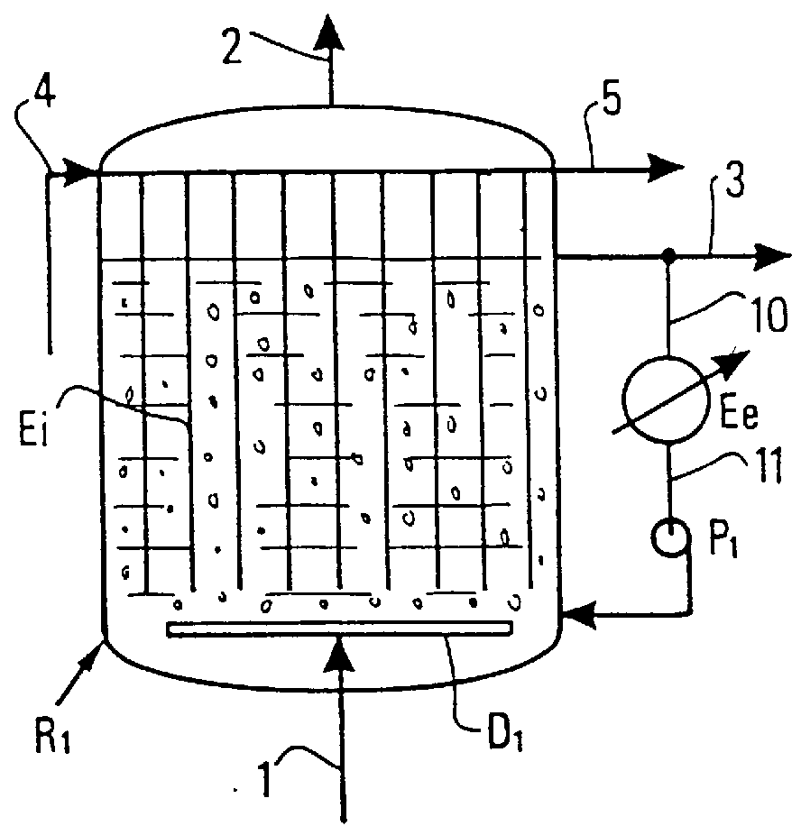
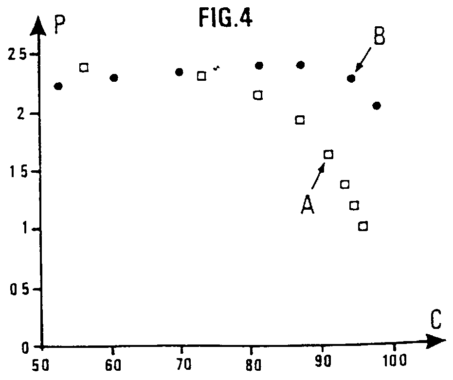
Comparison of the Productivity of a Reactor Slurry Operating With Recirculation of the Liquid Phase With That of a Conventional Bubble Column of the Same Size, For the Fischer-Tropsch Synthesis--Case of an Isothermal Co-current Reactor With an Upflow of Gas And Liquid

This comparison was based on the numerical results obtained with a software engineering program for the reactor specially developed for the design of a slurry reactor for the Fischer-Tropsch synthesis. The model used for this study was an axial dispersion model, the equations for which were as follows: ##EQU1## i: index representing the gas phase or the liquid phase; j: index for the constituent for which the material balance is calculated (CO, H.sub.2, H.sub.2 O);

C.sub.j : concentration of j in the liquid phase;

C.sub.j *: concentration of j in the liquid phase at equilibrium;

r: rate of synthesis reaction;

.epsilon..sub.I : degree of retention of phase i;

u.sub.i : superficial velocity in phase i;

F.sub.j.sup.i : molar flu...


PUM

PropertyMeasurementUnit
diameteraaaaaaaaaa
pressureaaaaaaaaaa
pressureaaaaaaaaaa

Abstract

The invention concerns a process for optimal operation of a slurry bubble column containing a suspension of solid particles in a liquid, characterized in that a gas phase containing the reactant(s) required for the production of the desired products is injected in the form of bubbles close to the lower extremity of said reactor and at least a portion of the liquid fraction and optionally of the solid fraction of said suspension is recirculated, drawn off from close to one extremity of said reactor and reintroduced close to the other extremity of said reactor, with a liquid flow rate U1 in the reactor which is at least equal to and preferably greater than the sedimentation rate Us of the solid particles. The invention also concerns an apparatus for optimal operation of the process. Finally, the invention concerns the use of the process and apparatus in the Fischer-Tropsch synthesis.

Description

SUMMARY OF INVENTIONThe present invention concerns a process for optimal operation of a slurry bubble column containing three phases, namely a liquid phase, a solid phase and a gas phase. In this type of column, particles are held in suspension in the liquid by introducing gas bubbles close to the lower portion of the column. The present invention also concerns an apparatus for operating the bubble column under the optimal conditions of the present process. It also concerns the application of this process and apparatus to the synthesis of essentially linear and saturated hydrocarbons, preferably containing at least 5 carbon atoms per molecule, by reduction of synthesis gas CO--(CO.sub.2)--H.sub.2, i.e., a mixture of carbon monoxide and hydrogen, and optionally carbon dioxide, using the Fischer-Tropsch process. More particularly, the present invention is applicable to exothermic reactions which occur at high temperature, for example above 100.degree. C., normally above 150.degree. C....

Claims


Application Information

Patent Timeline
Patent Type & Authority Patents(United States)
IPC IPC(8): B01J8/00B01J8/18B01J8/22B01J8/20C07C1/02C07C1/04C07C1/12C07C9/00C10G2/00
CPCB01J8/0005B01J8/1836B01J8/226B01J8/228C10G2/342B01J2208/00132B01J2208/0015B01J2208/00283B01J2208/00123
Inventor CASANAVE, DOMINIQUEGALTIER, PIERREVILTARD, JEAN-CHARLES
Owner INST FR DU PETROLE
Why Eureka
Try Eureka