Self-priming centrifugal pump

a centrifugal pump and self-priming technology, which is applied in the direction of piston pumps, positive displacement liquid engines, liquid fuel engines, etc., can solve the problems of reducing efficiency, prolonging the duration of priming the pump, and general unsatisfactory methods of priming chemical pumps

Inactive Publication Date: 2000-06-06
CHANG WAN TE
View PDF2 Cites 20 Cited by
  • Summary
  • Abstract
  • Description
  • Claims
  • Application Information

AI Technical Summary

Problems solved by technology

These means of priming chemical pumps are generally unsatisfactory because of the corrosive nature of the liquids being handled.
However, every time when the self-priming pump starts to move liquid from the supply, air within the pipin

Method used


Image

  • Self-priming centrifugal pump
  • Self-priming centrifugal pump
  • Self-priming centrifugal pump

Examples


Embodiment Construction

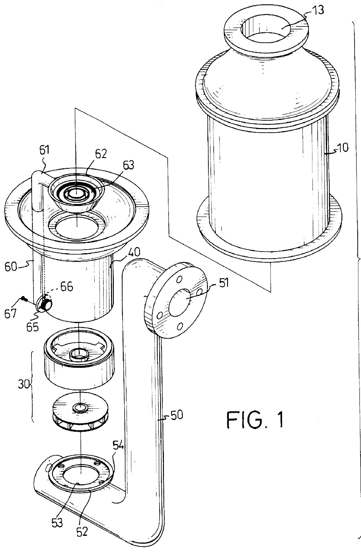
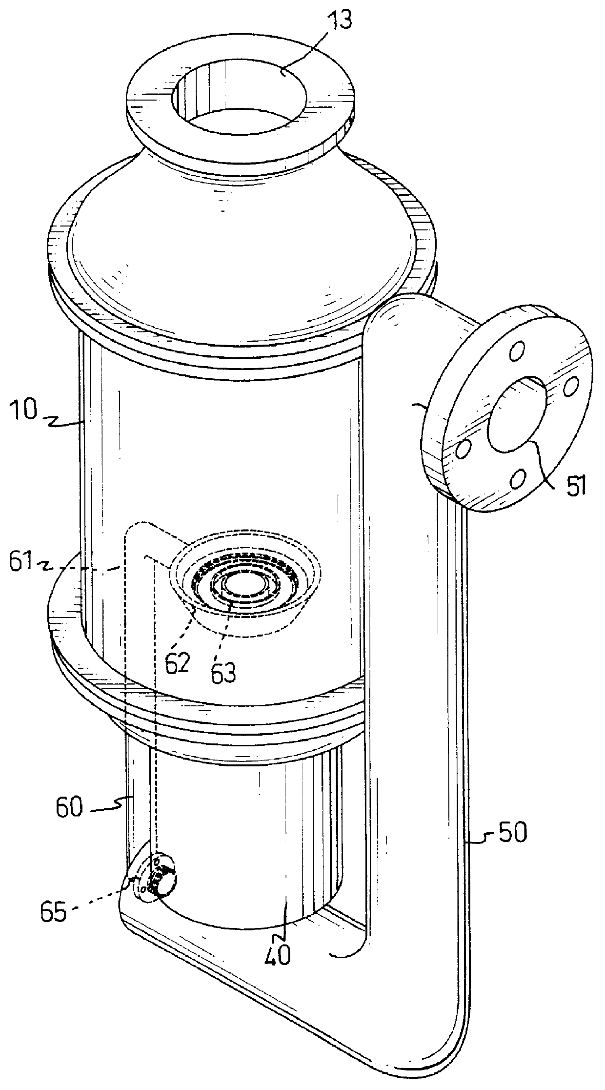
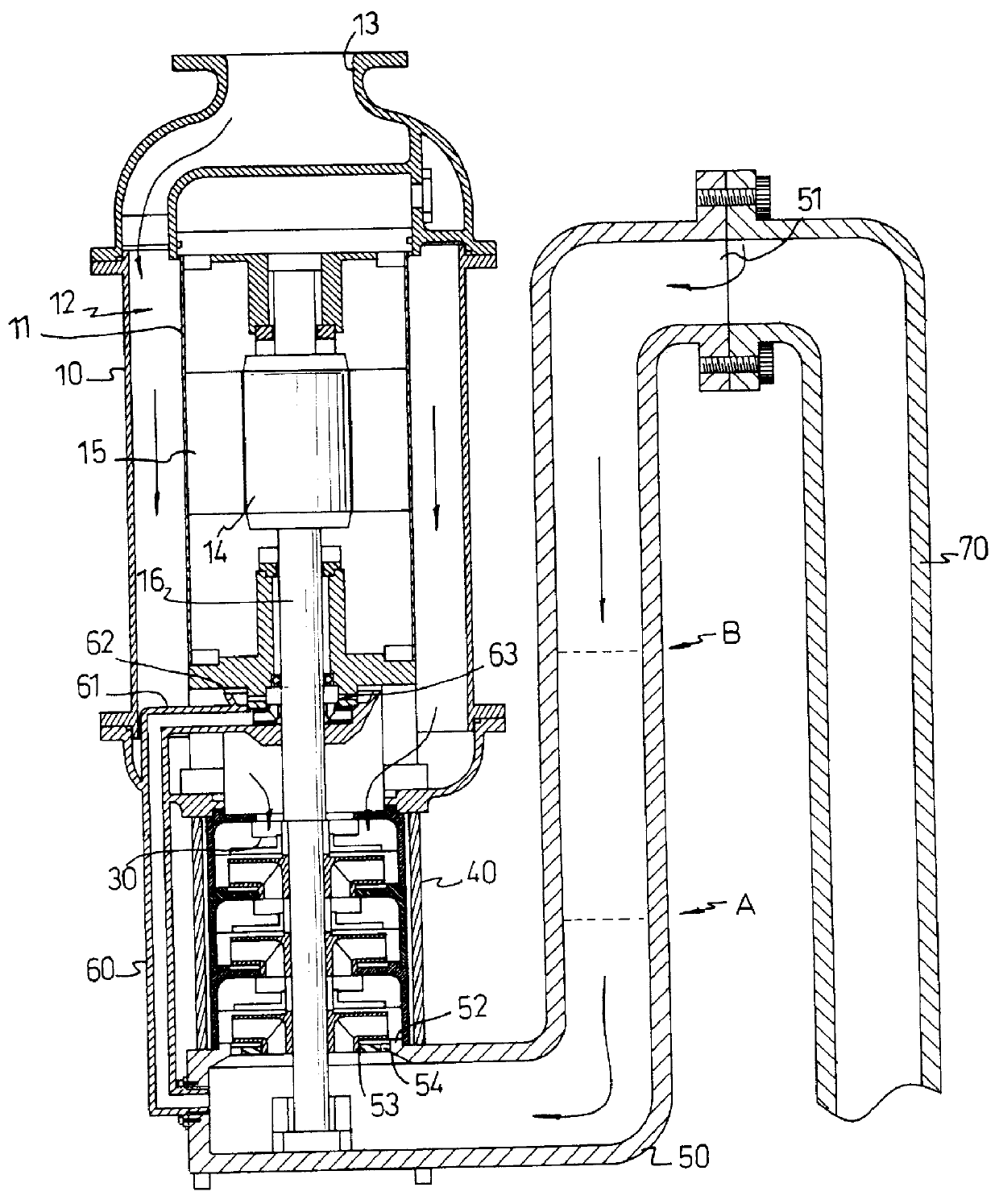
A self-priming centrifugal pump has the capability of efficiently removing the air from the suction piping. Removal of this air creates a partial vacuum in the suction line, allowing atmospheric pressure to force liquid from the source into piping between the pump and the source and into the pump, thereby establishing prime. Such a pump must be capable of forming a seal above the impeller so that atmospheric pressure cannot work back through the discharge line to break the vacuum. Finally, a self-priming pump must function efficiently as a standard centrifugal pump after it has been primed and establishes flow. No matter what design the centrifugal pump may have, it functions in the same manner. That is, it retains a certain amount of priming liquid when the pump is shut-down or loses prime, and the pump recirculates the priming liquid in such a way as to entrain air at its inlet side and to release it at its discharge side.

For this reason, the piping of the self-priming feature mus...


PUM


Abstract

A self-priming centrifugal pump has a recirculation tube connected between a hollow cylinder having a first set of impellers received therein and a first tube having liquid received therein and having a second set of impellers received in one end thereof, so that the suction lift of liquid is enhanced and the liquid flow subjected only to the gravity will also be expedited by the extra centrifugal effect created by the second impeller. Furthermore, there are provided with a plurality of through holes communicating with the first tube. Therefore, the amount of liquid flow back to the first tube is increased.

Description

1. Field of the InventionThe present invention relates to a self-priming centrifugal pump, in particular, a pump with a guiding tube and a set of impeller to expedite the flow of fluid downstream so as to achieve the purpose of draining fluid upward from water supply.2. Description of Related ArtA centrifugal pump will not move liquid unless it is primed. A pump is said to be "primed" when the pump casing and the suction piping are completely filled with liquid. Units that are located below the liquid level of the suction tank can be primped by merely opening the suction and discharge valves, thereby allowing liquid to flow into the pump by gravity. Conventional centrifugal pumps that are located above the suction level must be primed by some auxiliary means such as a vacuum pump, or a ejector. These means of priming chemical pumps are generally unsatisfactory because of the corrosive nature of the liquids being handled. Foot valves are sometimes used on the lower end of the suction...

Claims


Application Information

Patent Timeline
IPC IPC(8): F04D9/00F04D9/02
CPCF04D9/02F04D9/007F04D9/005
Inventor CHANG, WAN-TE
Owner CHANG WAN TE
Why Eureka
Try Eureka