Resilient pipe gasket

Inactive Publication Date: 2000-07-04
SCP +1
View PDF12 Cites 59 Cited by
  • Summary
  • Abstract
  • Description
  • Claims
  • Application Information

AI Technical Summary

Benefits of technology

It is another object of the present invention to provide a resilient pipe gasket for corrugated pipes which will not become displaced during joining of two pipes.
It is yet another object

Problems solved by technology

However, the disadvantage exists that prior art gaskets on an outer surface of a corrugated pipe are easily displaced during insertion of the first pipe into the bell of the second pipe.
This results in poorly sealed joints between pipes.
An Additional disadvantage exists that gaskets for drain and sewer pipes are typically fitted in the valleys between corrugation ribs

Method used


Image

  • Resilient pipe gasket
  • Resilient pipe gasket
  • Resilient pipe gasket

Examples


Embodiment Construction

Preferred embodiments of the present invention are now described with reference to FIGS. 1 to 4.

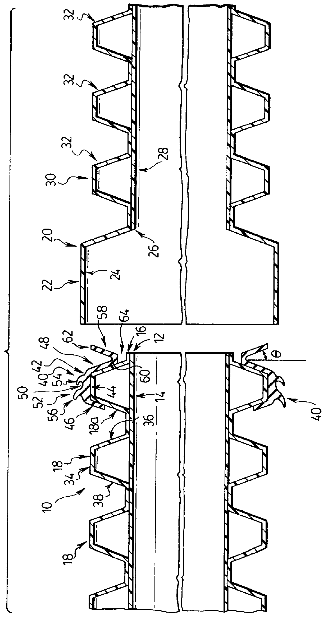
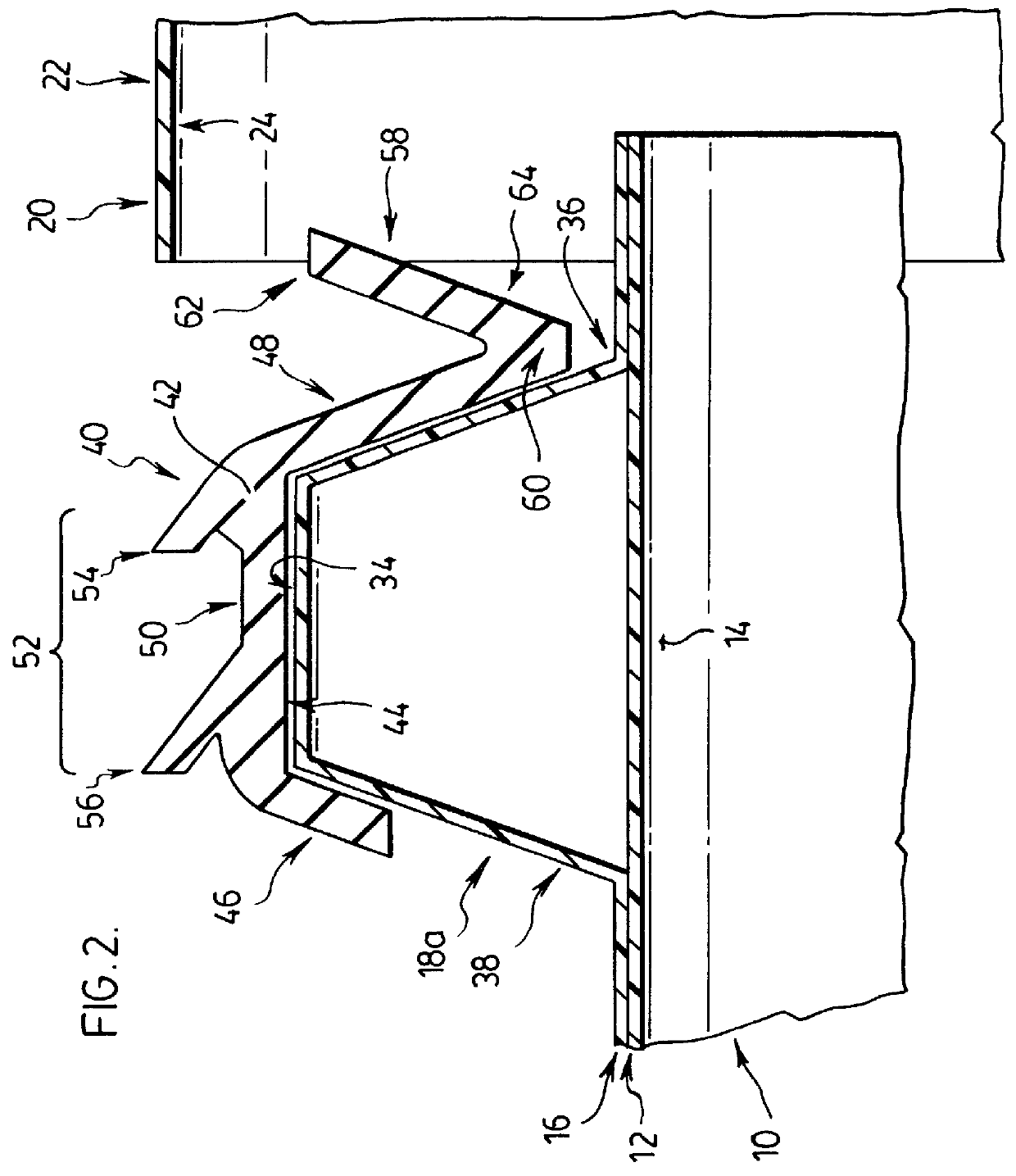
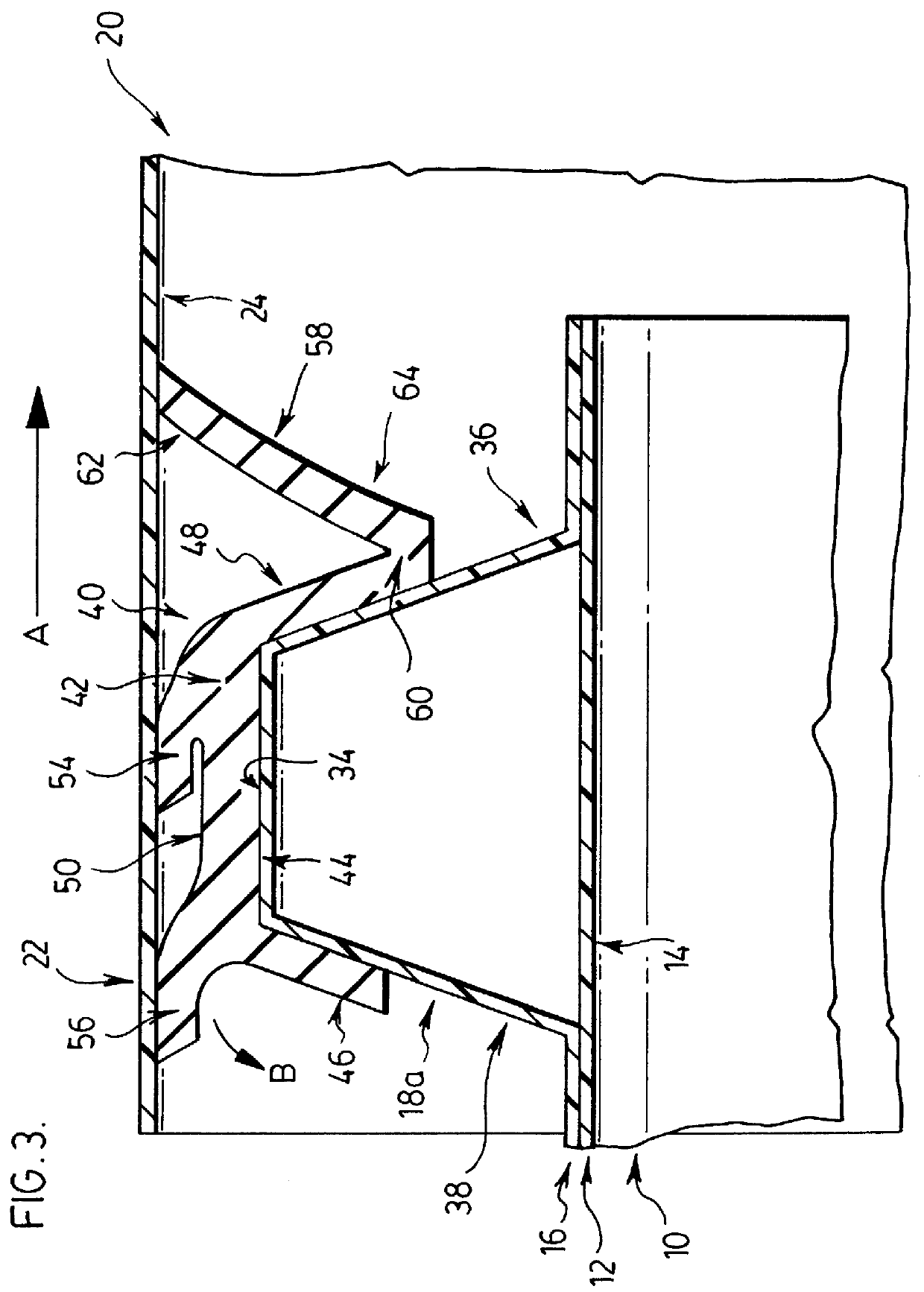
FIG. 1 is a cross-sectional view in the longitudinal direction illustrating an end of a first pipe 10 having two layers, an inner layer 12 having a smooth inner surface 14 and an outer corrugated layer 16 having a plurality of circumferential, outwardly extending ribs 18. In a typical application of the present invention, first pipe 10 is a drain or sewer pipe to be buried in soil, for example along a highway.

The layers 12 and 16 of first pipe 10 are relatively thin and are preferably made of a plastic material such as polyethylene. The provision of ribs 18 in corrugated layer 16 increases the rigidity of first pipe 10.

The first pipe 10 is adapted to mate with second pipe 20. The end of first pipe 10 shown in FIG. 1 is adapted to be received in the end of a second pipe 20. As shown in FIG. 1, second pipe 20 has an enlarged bell 22 with a smooth inner surface 24 into which the end of first...


PUM

PropertyMeasurementUnit
Flow rateaaaaaaaaaa
Flexibilityaaaaaaaaaa
Distanceaaaaaaaaaa

Abstract

A resilient gasket is disclosed for providing a seal between corrugated pipes having a plurality of concentric ribs on their outer surfaces, such as drain and sewer pipes to be buried in soil. The gasket comprises a base which is received around a first pipe over top of a rib adjacent an end of the first pipe, with an inner surface adapted to mate with a radially outer surface of the rib, and with legs adapted to extend along forward and rearwardly-sloped faces of the rib. The outer surface of the base is provided with sealing elements to engage the inner surface of the bell adjacent the end of a second pipe. The gasket also has a flap extending outwardly and forwardly from the forwardly extending leg. The flap and the forward leg form a V-shaped member. The flap engages the inner surface of the bell when the first pipe is inserted into the second pipe, and the gasket is rotated rearwardly relative to the rib. When the flap engages the inner surface of the bell, it prevents further rearward displacement of the gasket relative to the rib, thus preventing displacement of the gasket from the rib. The gasket also helps prevent gasket blowout during periods of unusually heavy water flow through the pipes.

Description

FIELD OF THE INVENTIONThis invention relates to gaskets for forming at least soil-tight joints between pipes or pipe fittings.BACKGROUND OF THE INVENTIONPipes having outer corrugated surfaces are known for use as drain and sewer pipes to be buried in soil. To provide at least a soil-tight seal, and preferably a water-tight seal, between two lengths of pipe, a gasket is provided extending circumferentially around the outer surface of a first pipe which is to be inserted into the bell of a second pipe.However, the disadvantage exists that prior art gaskets on an outer surface of a corrugated pipe are easily displaced during insertion of the first pipe into the bell of the second pipe. This results in poorly sealed joints between pipes.An Additional disadvantage exists that gaskets for drain and sewer pipes are typically fitted in the valleys between corrugation ribs and require relatively large volumes of gasket material. Thus, it is difficult to obtain sufficient compression because ...

Claims


Application Information

Patent Timeline
IPC IPC(8): F16J15/32
CPCF16J15/32Y10S285/903F16L25/0054F16L21/03
Inventor GREGOIRE, BERNARDSHARMA, PARDEEP K.
Owner SCP
Why Eureka
Try Eureka