Optical fiber ribbon midspan splitter device

a splitter device and optical fiber ribbon technology, applied in the direction of optics, fibre mechanical structures, instruments, etc., can solve the problems of loose fibers in the area being accessed, difficult to split optical fiber groups from optical fiber ribbons, and inconvenient methods

Inactive Publication Date: 2000-07-18
SUMITOMO ELECTRIC LIGHTWAVE
View PDF4 Cites 10 Cited by
  • Summary
  • Abstract
  • Description
  • Claims
  • Application Information

AI Technical Summary

Problems solved by technology

However, when the ribbon is accessed in midspan in circumstances where the end of the optical fiber ribbon is not available, it is quite difficult to split groups of optical fibers from an optical fiber ribbon.
However, these methods are not particularly advantageous since removing the ribbon matrix results in loose fibers in the area being accessed.
Unfortunately, separate steps are typically required to rebuild a section of optical fiber ribbon containing the required number of optical fibers so that mass splicing can be performed.
However, applicants do not believe that any of the references either singly or in combination disclose the midspan splitter tool invention for separating optical fiber ribbons into subgroups for mass splicing.

Method used


Image

  • Optical fiber ribbon midspan splitter device
  • Optical fiber ribbon midspan splitter device
  • Optical fiber ribbon midspan splitter device

Examples


Embodiment Construction

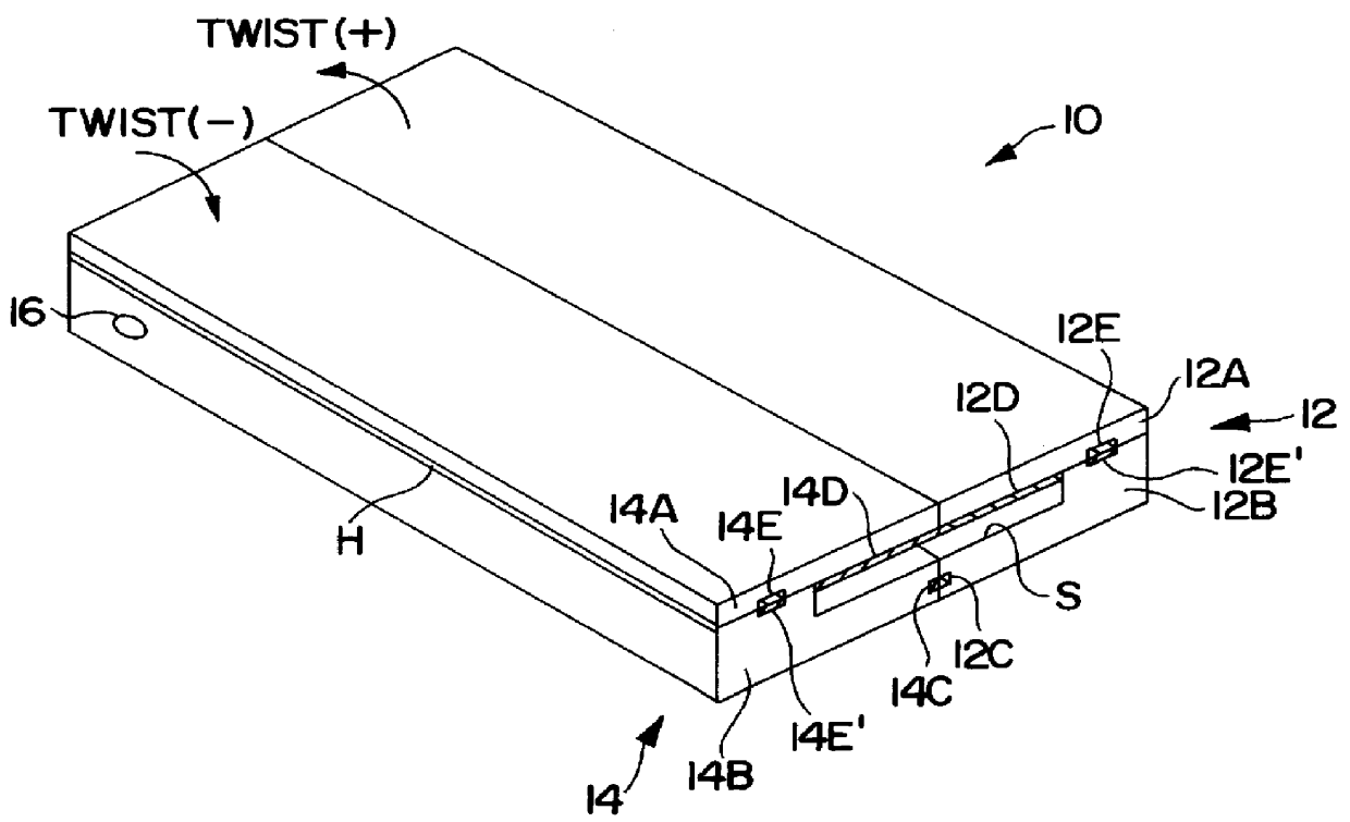
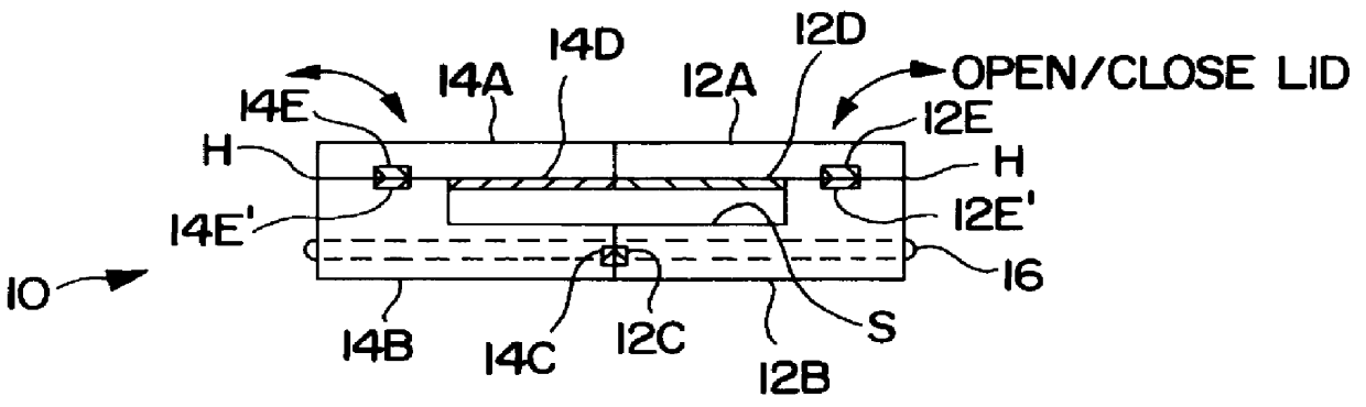
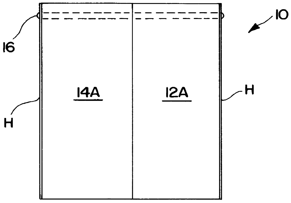
Referring now to FIGS. 6A and 6B, an alternative embodiment of the optical fiber ribbon midspan splitter device is shown and generally designated 100. Device 100 consists of a base 102 defining a vertical slot 102A therein for an optical fiber ribbon R to be fully received across the entire length thereof (see FIGS. 6A and 6B). Two clamps 102B and 102C are located on opposing ends of device 100 for being (1) tightened or otherwise adjusted in order to secure optical fiber ribbon R in place in vertical slot 102A of the base of device 100 and (2) loosened or otherwise adjusted in order to release engagement of ribbon R by clamps 102B and 102C within vertical slot 102A. A circular slide 102D is mounted in a cut-out or recessed portion 102E located in the medial portion of midspan splitter device 100. Circular slide 102D is mounted in recessed portion 102E and adapted for transverse movement from an unload position to a load position wherein the portion of circular slide 102D extending ...


PUM


Abstract

A optical fiber ribbon midspan splitter tool for quick and easy midspan splitting of an optical fiber ribbon into separate ribbon sub-groups for mass splicing. The device comprises a pair of splitter tool sections each having a base and a lid and defining a slot through the splitter tool. The pair of elongate tool sections are rotatably mounted about a transverse hinge through both sections adjacent one end of the tool. The pair of lids are each mounted to a respective one of a pair of bases so as to open upwardly and outwardly for placement of an optical fiber ribbon in the slot defined within the two adjacent bases of the splitter tool. Magnets are provided at the juncture of the splitter tool sections for maintaining the splitter tool sections in releasable alignment, and a pair of magnets are provided in each splitter tool section at the juncture of the base and the lid for releasably maintaining the base and lid in abutting enclosed relationship. Thus, an optical fiber ribbon can be inserted into the tool and the pair of splitter tool sections twisted in opposite directions to split the ribbon into two separate sub-ribbons for midspan mass splicing. A second embodiment of the splitter tool is also described.

Description

The present invention relates to optical fiber ribbon, and more particularly to a device for quickly and easily splitting an optical fiber ribbon midspan into separate ribbon subgroups for mass splicing.RELATED ARTOptical fiber cables containing optical fiber ribbons have been used in the telecommunications industry for quite a number of years. As is well known to those skilled in the art, an optical fiber ribbon consists of a plurality of optical fibers that are longitudinally laid parallel and adjacent to one another and then edge-bonded or encapsulated together with a plastic matrix material. Optical fiber ribbons normally incorporate 4, 6, and 12 optical fibers, although other numbers of optical fibers can be used in an optical fiber ribbon.As is also well known to one skilled in the art, splicing is the process of joining optical fibers together. While single splicing involves joining one fiber at a time, mass splicing such as typically used for optical fiber ribbons involves j...

Claims


Application Information

Patent Timeline
Patent Type & Authority Patents(United States)
IPC IPC(8): G02B6/44
CPCG02B6/4498G02B6/567
Inventor LINDSAY, JR., RONALD G.SARBELL, JOHN P.
Owner SUMITOMO ELECTRIC LIGHTWAVE
Why Eureka
Try Eureka