Tube connection, in particular, for connecting two tubular fuselage portions of a missile

Inactive Publication Date: 2000-08-08
BODENSEEWERK GERATETECHNIK GMBH
View PDF13 Cites 19 Cited by
  • Summary
  • Abstract
  • Description
  • Claims
  • Application Information

AI Technical Summary

Benefits of technology

to provide a highly stable and highly stiff connection f

Problems solved by technology

This deformation consumes a large proportion of the screwing force.
The positive locking achieved is bad.
The prior art tube connection is not satisfactory, especially when tubular fuselage portions for highly agile missiles are t

Method used


Image

  • Tube connection, in particular, for connecting two tubular fuselage portions of a missile

Examples


Embodiment Construction

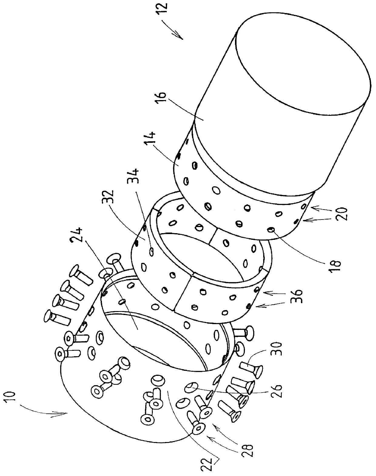
Referring to FIG. 1, numeral 10 designates a first tubular fuselage portion. The first tubular fuselage portion 10 is to be connected to a second tubular fuselage portion 12.

The tubular fuselage portions 10 and 12 are the tubular portions of the fuselage of a missile.

The tubular fuselage portion 12 has a rim 14. The rim 14 has a smaller diameter than the remaining portion 16 of the tubular fuselage portion 12. In the rim 14, bores 18 are provided in two rows 20 along the circumference of the rim 14.

The tubular fuselage portion 10 has a rim 22. The rim 22 has an inner diameter which, except for a small jointing tolerance, corresponds to the outer diameter of the rim 14 of the other tubular fuselage portion 12. This inner diameter may be smaller than the inner diameter of the remaining portion 24 of the tubular fuselage portion 10. Bores 26 are provided in the rim 22, in two rows 28 along the circumference of the rim 22. The bores 26 are formed, such that, the head of the screws 30 to...


PUM


Abstract

A connection is described for connecting two tubular fuselage portions of a missile. The inner diameter of the rim of a first tubular fuselage portion to be connected with a second tubular fuselage portion corresponds to the outer diameter of the rim of the second tubular fuselage portion to be connected to the first tubular fuselage portion, deducting a jointing tolerance, The rims of the tubular fuselage portion to be connected are provided with radial bores to accommodate connection screws, Clamp segments are mounted in the second tubular fuselage portion along the inner circumference thereof. The clamp segments define threaded bores, connection screws being screwed into these threaded bores.

Description

The invention relates to a connection for connecting two tubular fuselage portions of a missile with two inter-engaging tubular sections.PRIOR ARTIn prior art tube connections, tube portions which have different diameters in their rim regions to be connected, are pushed into each other and are connected by radial screws. In order to achieve a positive locking the inner tube portion is widened or the outer tube portion is compressed, when tightening the screws. This deformation consumes a large proportion of the screwing force. The positive locking achieved is bad.The prior art tube connection is not satisfactory, especially when tubular fuselage portions for highly agile missiles are to be interconnected. With such missiles, extreme stresses occur on the tube connections.From German patent application no. 196 15 7161--not yet published--a tube connection is known in which the rim regions to be connected consists of two circumferential sections of different diameters. The inner diame...

Claims


Application Information

Patent Timeline
IPC IPC(8): F42B15/36F42B15/00
CPCF42B15/36
Inventor BROSS, DIRKKNAPP, KLAUS-DIETERFISCH, PETER G.
Owner BODENSEEWERK GERATETECHNIK GMBH
Why Eureka
Try Eureka