Positioning hinge having a cam block

a technology of positioning hinge and cam block, which is applied in the direction of instruments, portable computer details, electrical apparatus casings/cabinets/drawers, etc., and can solve the problem of inconvenience in operation

Inactive Publication Date: 2000-08-29
LIN DAVYS
View PDF7 Cites 82 Cited by
  • Summary
  • Abstract
  • Description
  • Claims
  • Application Information

AI Technical Summary

Benefits of technology

The purpose of this invention is to create a mechanism for lifting and angling the screen of a laptop or other mobile device that allows it to automatically adjust its brightness based on external factors like sunlight or dark environments. This makes it easier to see the screen even without adding any extra equipment or power sources.

Problems solved by technology

The technical problem addressed in this patent text is the inconvenience and difficulty of lifting and adjusting the hinges of conventional portable computers' LCD displays to a comfortable viewing angle. This problem needs to be solved to improve the user experience when using these computers.

Method used


Image

  • Positioning hinge having a cam block
  • Positioning hinge having a cam block
  • Positioning hinge having a cam block

Examples


fourth embodiment

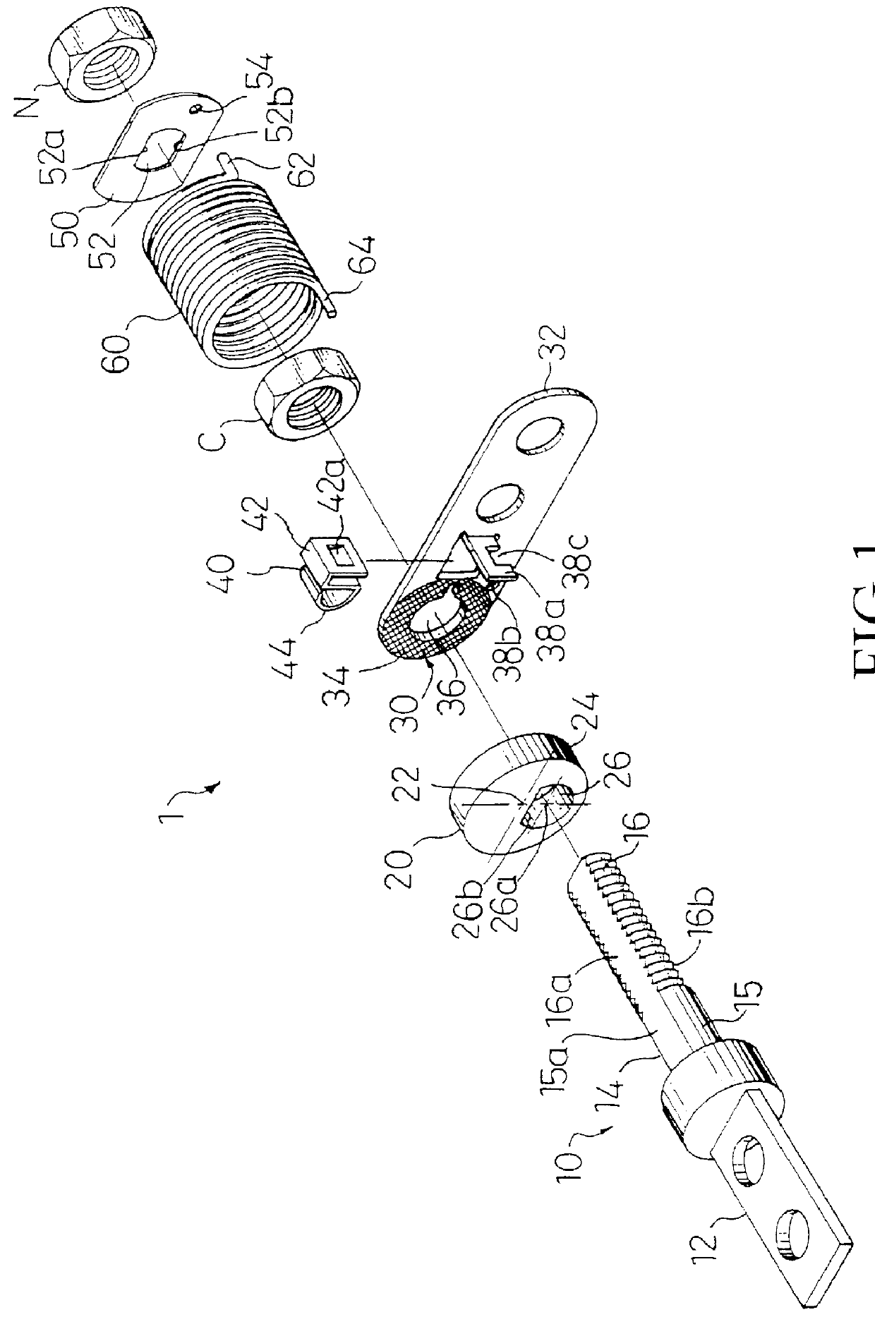
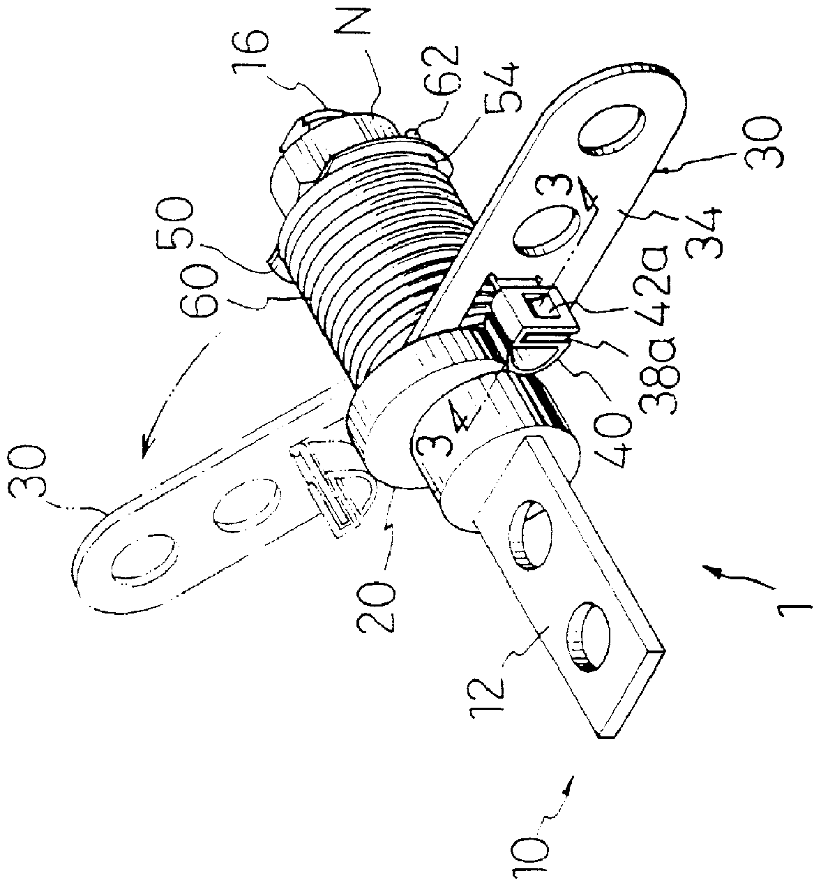
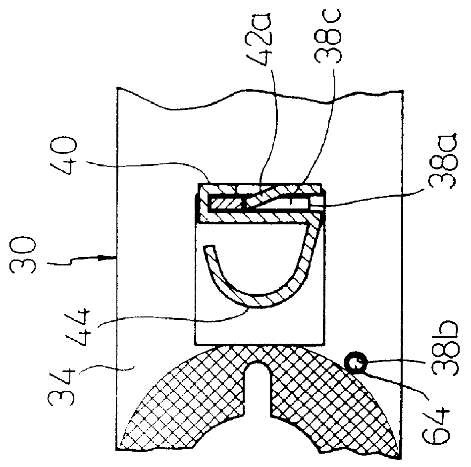
FIGS. 8 and 8A illustrate the assembled and exploded, perspective views of this invention. The positioning hinge 100 mainly comprises a pivotal member 110, a pivotal base 120, a torsion spring 130, a cam block 140, a resilient friction member 150, and a fastening member N.

The pivotal member 10 includes a mounting end 112 and a rotary shaft 114, and is preferred to be formed with a channel 116. The mounting end 112 is formed with a hole H to allow the pivotal member 110 to be secured to the main unit M. The rotary shaft 114 includes a pivotal axis and is preferred to be extended in a columnar configuration.

The pivotal base 120 includes a mounting end 122 for mounting the pivotal base 120 to an LCD display D, and a first support 124, wherein the first support 124 is substantially perpendicular to the rotary shaft 114 of the pivotal member 110 and formed with a pivotal opening 128 through which the rotary shaft 114 passes.

The torsion spring 130 may be provided around the rotary shaft 1...

fifth embodiment

FIGS. 10 and 11A illustrate the assembled and exploded, perspective views of this invention. The positioning hinge 200 comprises a pivotal member 210, a pivotal base 220, a torsion spring 230, a cam block 240, a resilient friction member 250, and a fastening member N'. The pivotal member 210 includes a mounting end 212 and a rotary shaft 214. The pivotal base 220 includes a mounting end 222, a first and a second supports 224, 226 that are spaced apart from each other and formed with pivotal openings 228. The first and the second supports 224, 226 are substantially perpendicular to the rotary shaft 214. The torsion spring 230 includes a first end 232 and a second end 234 that respectively urge against and connect to the pivotal member 210 and the pivotal base 220. In this embodiment, a detachable stop plate 270 is non-rotationally provided around the rotary shaft 214. The stop plate 270 includes a stop portion 272 that is connected to the second end 232 of the torsion spring 230. The...


PUM


Abstract

Disclosed is a positioning hinge for use in a portable computer or an electronic dictionary having a main unit and an LCD display, the hinge comprising a pivotal member for mounting the hinge to the main unit; a substantially disk-shaped cam block non-rotatably provided around the pivotal member; a pivotal base rotatably for mounting the hinge to the LCD display. By biasing against the cam block, this invention allows the LCD display of a portable computer to pivot with respect to the main unit so as to adjust the orientation of the LCD display e. This invention can be simply assembled, includes a low number of components, and is of a relatively compact size.

Description


Claims


Application Information

Patent Timeline
Owner LIN DAVYS
Why Eureka
Try Eureka