Surgical stapler

a surgical stapler and stapler technology, applied in the field of surgical staplers, can solve the problems of not being able to sterilize after use, being a relatively complicated mechanical instrument, and being difficult to reuse staplers,

Inactive Publication Date: 2000-10-17
ETHICON INC
View PDF63 Cites 1827 Cited by
  • Summary
  • Abstract
  • Description
  • Claims
  • Application Information

AI Technical Summary

Problems solved by technology

Reusable staplers, being a relatively complicated mechanical instrument, are difficult to sterilize after use.
However, delay occurs when a used cartridge is inadvertently reloaded in the stapler or a used cartridge is not removed before an att

Method used


Image

  • Surgical stapler
  • Surgical stapler
  • Surgical stapler

Examples


Embodiment Construction

Reference will now be made in detail to specific embodiments of the present invention which are conveniently described by reference to the accompanying FIGS. 1-13.

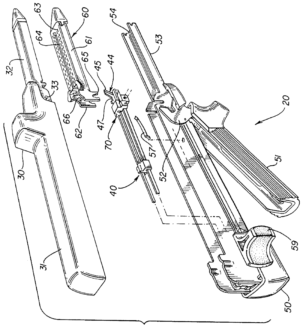
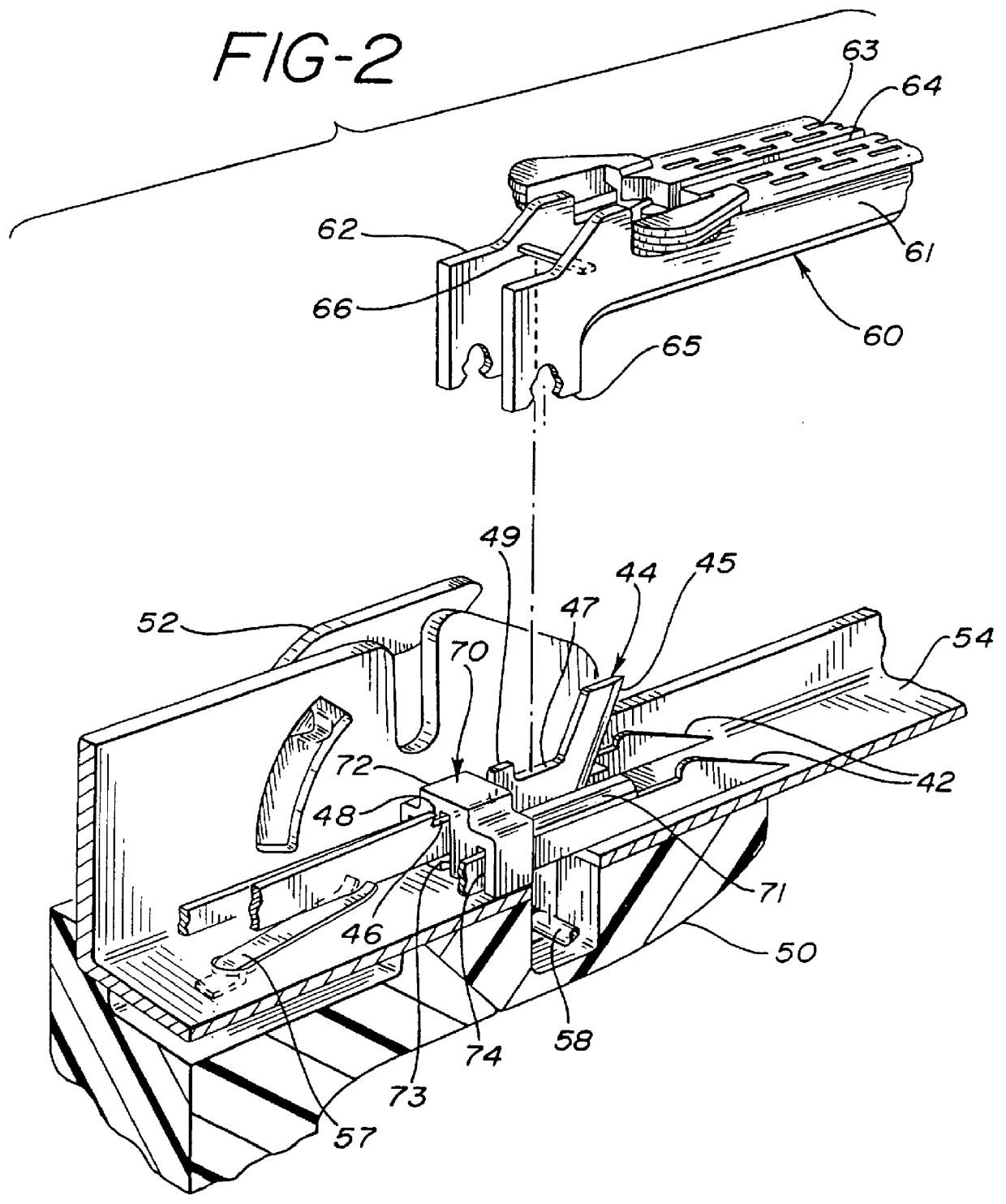
As seen in FIG. 1, a typical surgical stapler 20 comprises an upper piece 30, a firing means 40, a lower piece 50 and a staple cartridge 60.

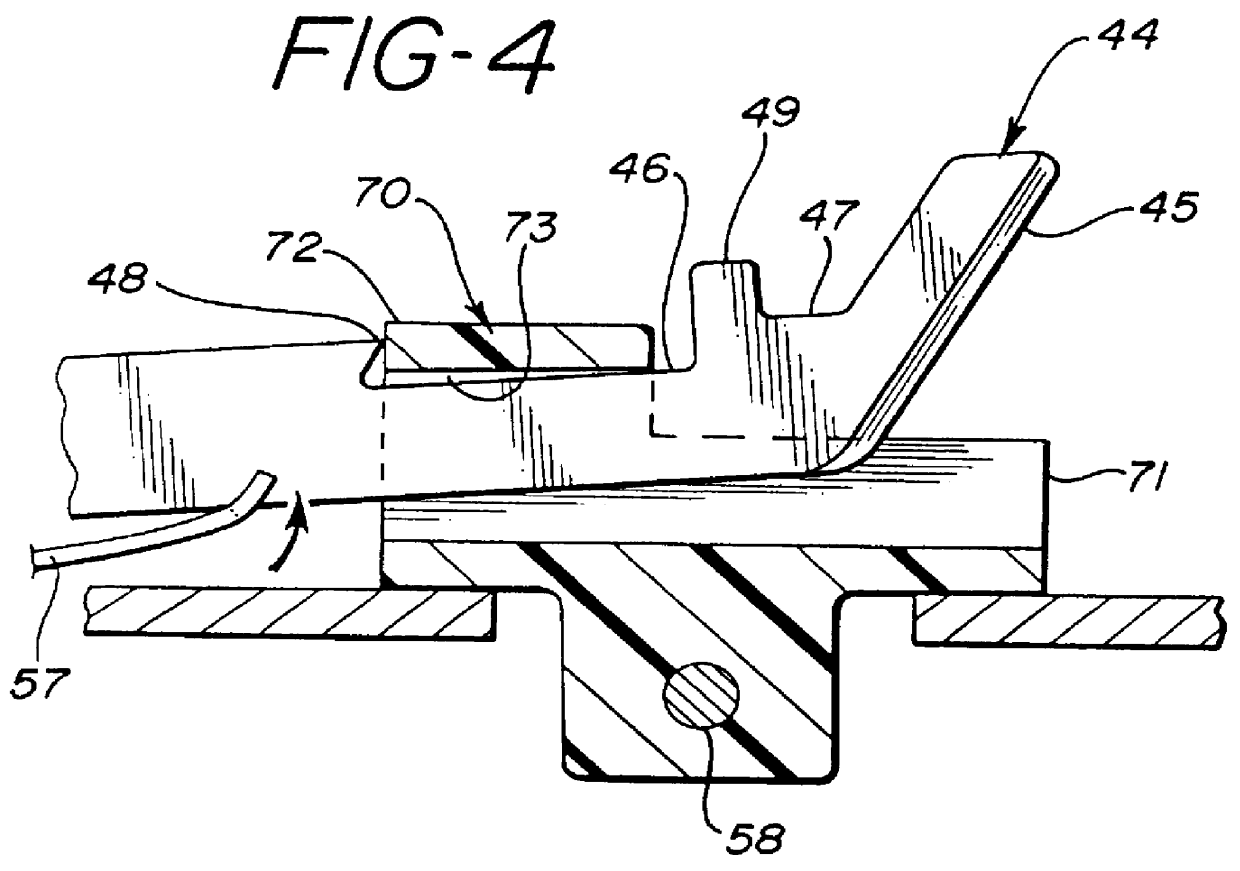
Staple cartridge 60 fits within the lower piece 50. Specifically, the front part of staple cartridge 60 fits into lower jaw channel 54. More specifically, the parallel side walls 61 of the staple cartridge 60 fit within the lower jaw channel 54. The back part of staple cartridge 60 has a breakable transverse member 66. This breakable transverse member 66 is placed on top of cartridge locking means 47 of firing means 40. At the same time two legs 65 secure staple cartridge 60 to lower piece 50. These legs 65 engage cylinder 58 of lower piece 50 in the second position, as best seen in FIG. 2.

In FIG. 1 the upper piece 30 has a rear upper handle portion 31 and a front upper jaw portion 32....


PUM


Abstract

The present invention relates to an improved surgical stapler that prevents refiring of a spent staple cartridge. More specifically, this invention includes a simple, inexpensive mechanical locking mechanism which prevents refiring of a spent staple cartridge by blocking the path of the firing and/or cutting means of the stapler.

Description

1. Field of the InventionThe present invention relates to an improved surgical stapler that prevents refiring of a spent staple cartridge. More specifically, this invention includes an inexpensive, simple and reliable mechanical locking mechanism that prevents refiring of a spent staple cartridge.2. Description of the Related ArtBefore surgical staplers were introduced surgeons had to spend a great deal of time sewing the tissue of patients back together. This was the most time intensive aspect of a surgical procedure. Surgical staplers have decreased the amount of time that a user spends sewing tissue back together.Another concern is whether the staplers used during procedures are sterile. Reusable staplers, being a relatively complicated mechanical instrument, are difficult to sterilize after use. Hence, it is desired that the surgical stapler be disposable. As more than one surgical stapler may be required in a surgical procedure, for economical reasons disposable surgical staple...

Claims


Application Information

Patent Timeline
IPC IPC(8): A61B17/068A61B17/072B25C5/00B25C5/16A61B19/00A61B17/115
CPCA61B17/07207B25C5/1686A61B2017/07214A61B2019/4873A61B2017/2945A61B2090/0814
Inventor SCHULZE, DALE R.SHERMAN, JON A.
Owner ETHICON INC
Why Eureka
Try Eureka