Case assembling structure of blower unit

a technology of blower unit and assembly structure, which is applied in the direction of machines/engines, manufacturing tools, liquid fuel engines, etc., can solve the problems of difficult to remove the upper case portion 101 from the die, and the case portion is not readily removable from the di

Inactive Publication Date: 2001-03-27
DENSO CORP
View PDF2 Cites 24 Cited by
  • Summary
  • Abstract
  • Description
  • Claims
  • Application Information

AI Technical Summary

Problems solved by technology

However, in the conventional blower unit, when a case portion for the blower unit is molded from a die, the case portion is not readily removable from the die, and each case portion must be divided into plural compl

Method used


Image

  • Case assembling structure of blower unit
  • Case assembling structure of blower unit
  • Case assembling structure of blower unit

Examples


Embodiment Construction

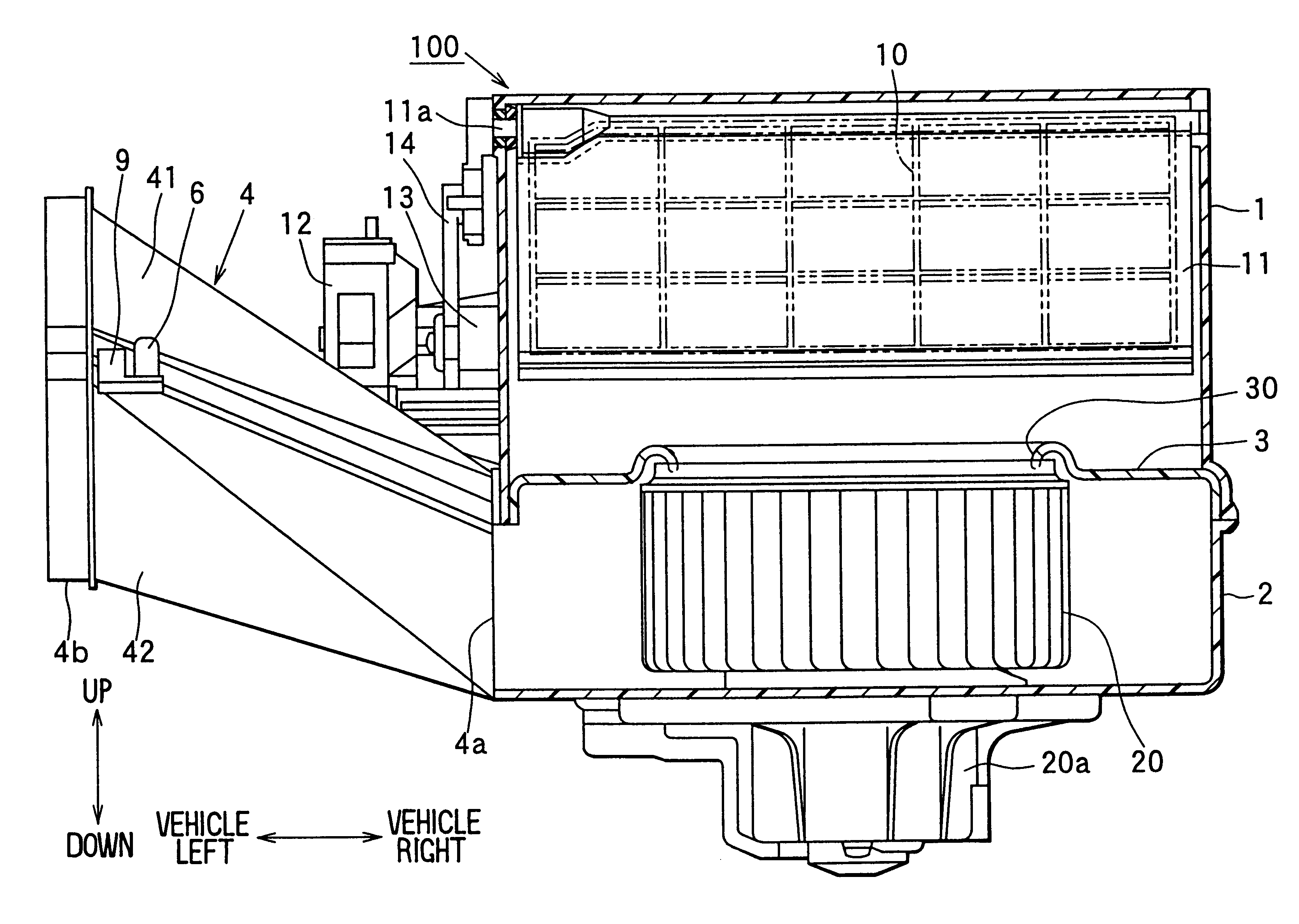
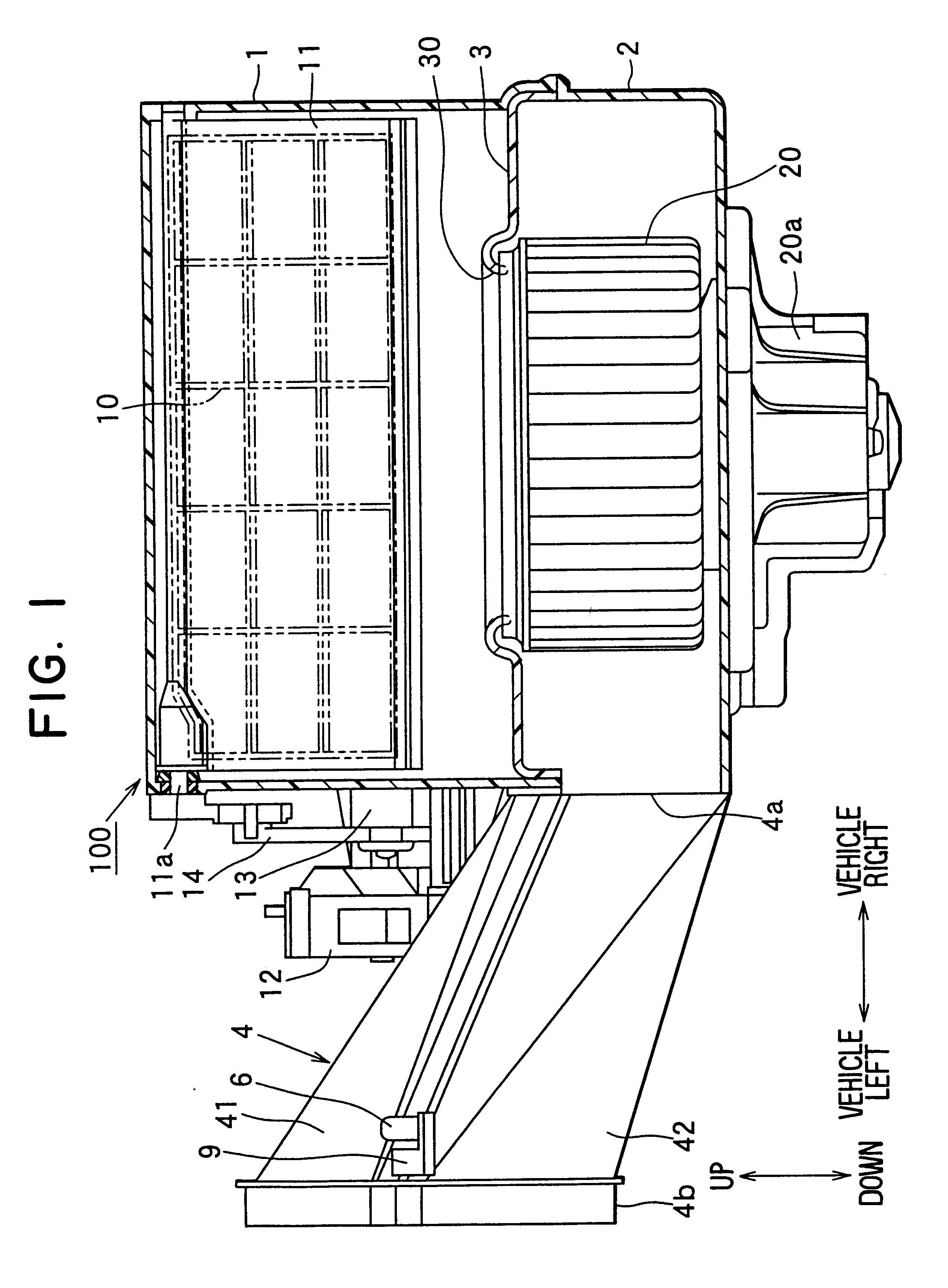
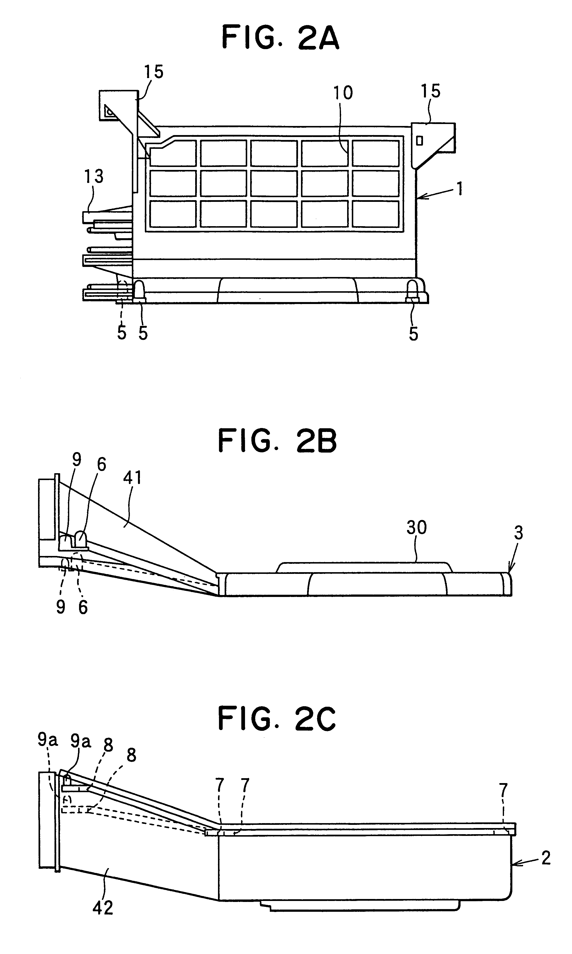
A preferred embodiment of the present invention will be described hereinafter with reference to FIGS. 1-2C. In the embodiment, a blower unit 100 of the present invention is typically applied to a vehicle air conditioner. A case of the blower unit 100 can be divided into an upper case portion 1 shown in FIG. 2A, a bell-mouth portion 3 shown in FIG. 2B and a lower case portion 2 shown in FIG. 2C. In the vehicle air conditioner, the blower unit 100 is disposed at an upstream air side of an air conditioning unit for controlling a temperature of air to be blown into a passenger compartment of a vehicle.

The blower unit 100 is disposed in the vehicle to correspond to the arrangement directions shown in FIG. 1. For example, in a vehicle having a left steering wheel, the air conditioning unit is disposed at an approximate center of an instrument panel in a vehicle right-left direction, and the blower unit 100 is disposed to be shifted from the air conditioning unit toward a right side in the...


PUM

PropertyMeasurementUnit
Fractionaaaaaaaaaa
Structureaaaaaaaaaa

Abstract

A blower unit includes a case divided into an upper case portion having an air introduction port, a lower case portion for accommodating a fan, and a bell-mouth portion interposed between the upper and lower case portion portions. An air leading port is provided in the bell-mouth portion, so that air sucked from the air introduction port is introduced to the fan through the air leading port. An attachment boss portion onto which a motor is attached is formed to protrude from an outer wall surface of the upper case portion. Air blown by the fan flows through a duct which is divided into a first member integrated with the bell mouth portion and a second member integrated with the lower case portion. The first member extends from the bell mouth portion obliquely to cover the attachment portion, and the second member extends from the lower case portion in the same direction as the first member to be engaged with the first member. Thus, each of the upper case portion, the bell-mouth portion integrated with the first member and the lower case portion integrated with the second member is simply molded from resin by using a die.

Description

1. Field of the InventionThe present invention generally relates to a blower unit for a vehicle air conditioner. More particularly, the present invention relates to a case assembling structure for securing a bell-mouth portion between upper and lower case portions of a blower unit.2. Description of Related ArtIn a conventional blower unit, a bell-mouth portion is interposed between an upper case portion for introducing air and a lower case portion for blowing air, and both of the upper and lower case portions are fastened by using a screw member, so that a case assembling structure of the upper and lower case portions is made simple. Each of the upper and lower case portions is made of resin. An air introduction port for introducing air is provided in the upper case portion, and a door for opening and closing the air introduction port is accommodated within the upper case portion. On the other hand, the lower case portion forms therein an air-blowing passage, and a fan is accommodat...

Claims


Application Information

Patent Timeline
IPC IPC(8): B60H1/00F04D29/60F04D29/62F04D29/42
CPCB60H1/00457F04D29/4226F04D29/626Y10T29/49826Y10T29/49359
Inventor NAKAMURA, TAKESHITSUNOOKA, TATSUOKANDA, HIROSHINAITO, NOBUYASU
Owner DENSO CORP
Why Eureka
Try Eureka