Double printing unit of a rotary printing machine

a technology of rotary printing machine and double printing unit, which is applied in the field of printing machines, can solve the problems of limited spacing and high cost of double printing uni

Inactive Publication Date: 2001-04-17
MANROLAND WEB SYST
View PDF14 Cites 61 Cited by
  • Summary
  • Abstract
  • Description
  • Claims
  • Application Information

AI Technical Summary

Problems solved by technology

However, in order to prevent the spur wheels from being disengaged, limits are placed on the extent of the spacing.
The guide rolls make the double printing unit costly.

Method used


Image

  • Double printing unit of a rotary printing machine
  • Double printing unit of a rotary printing machine
  • Double printing unit of a rotary printing machine

Examples


Embodiment Construction

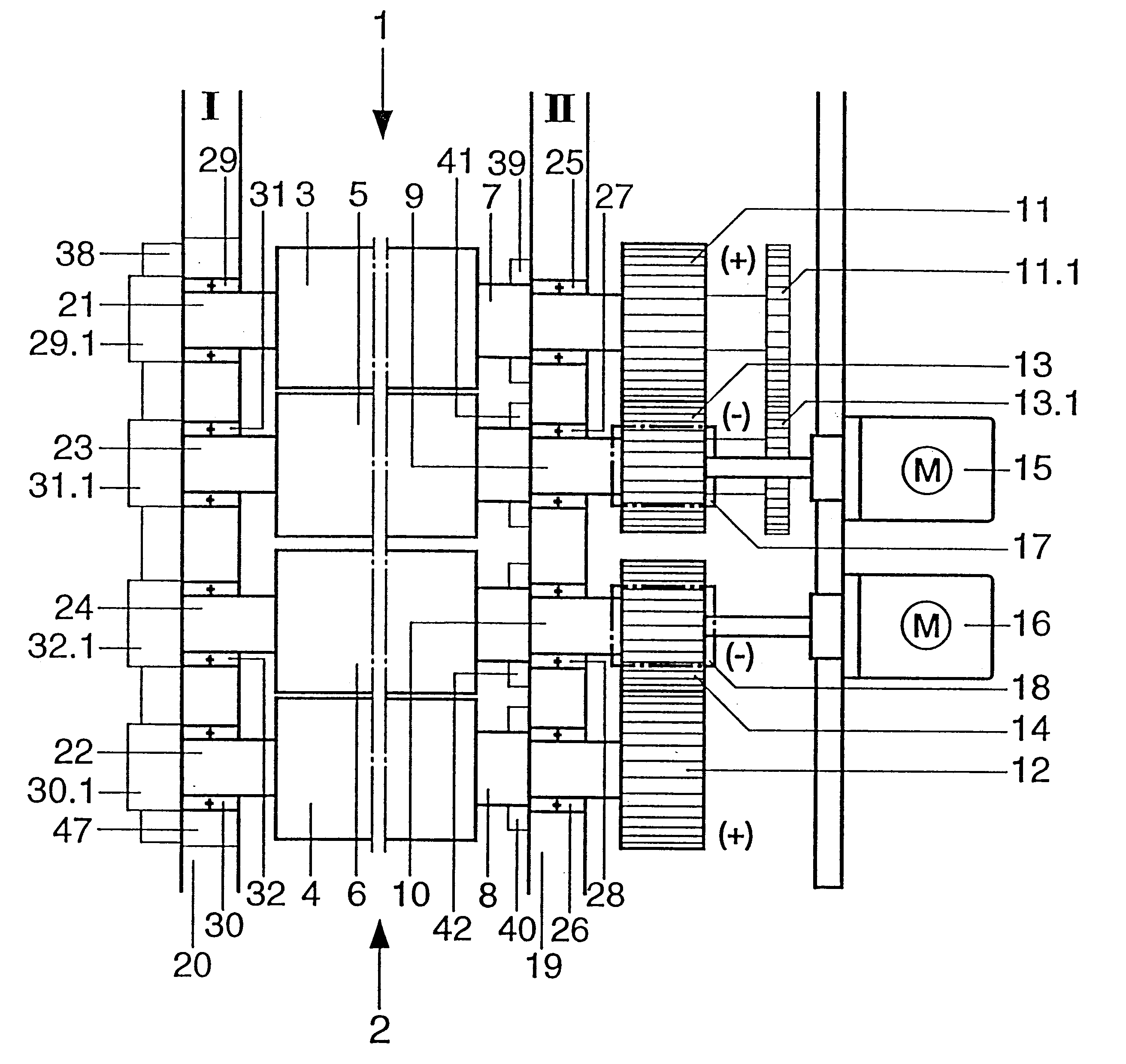
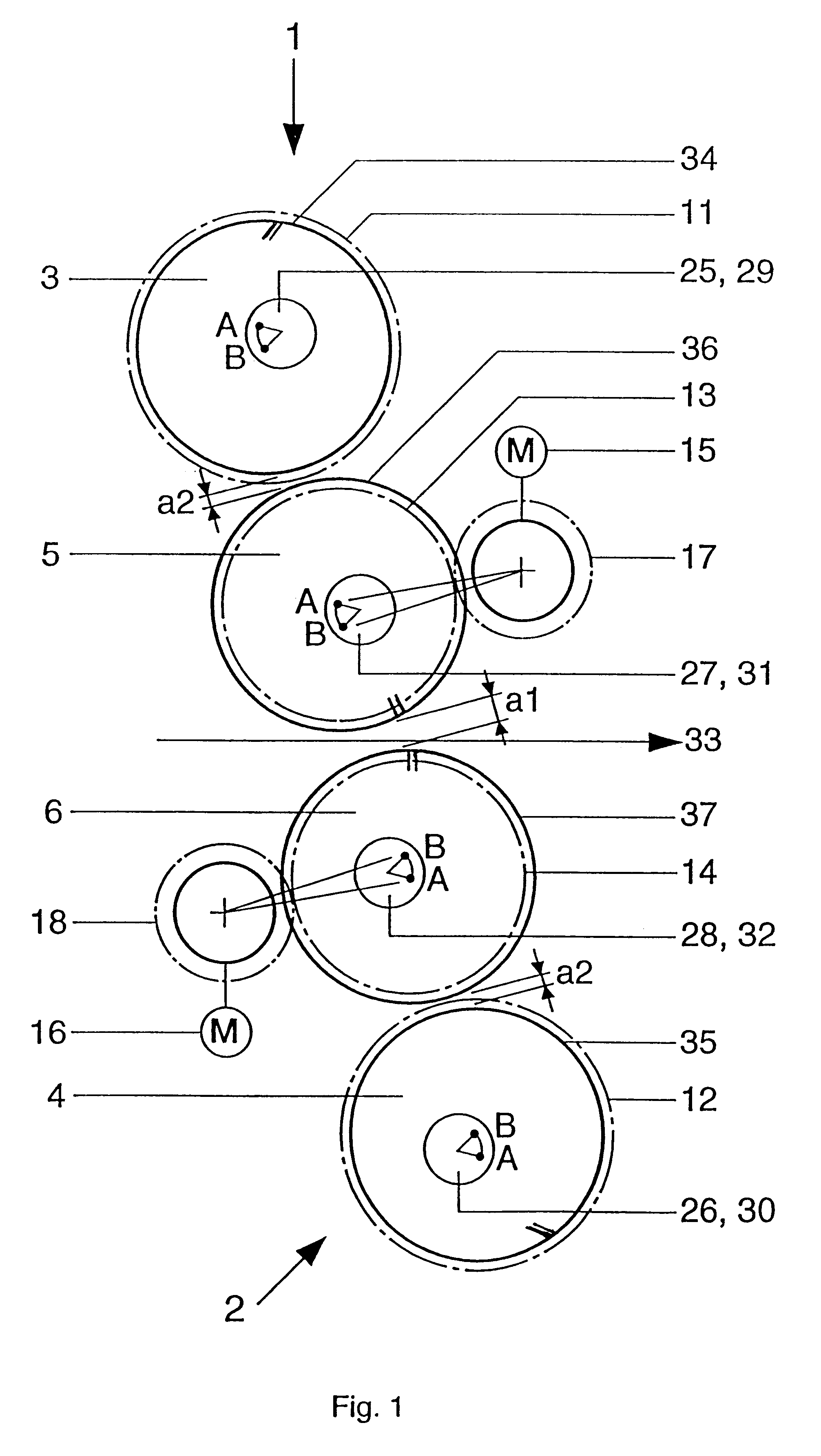
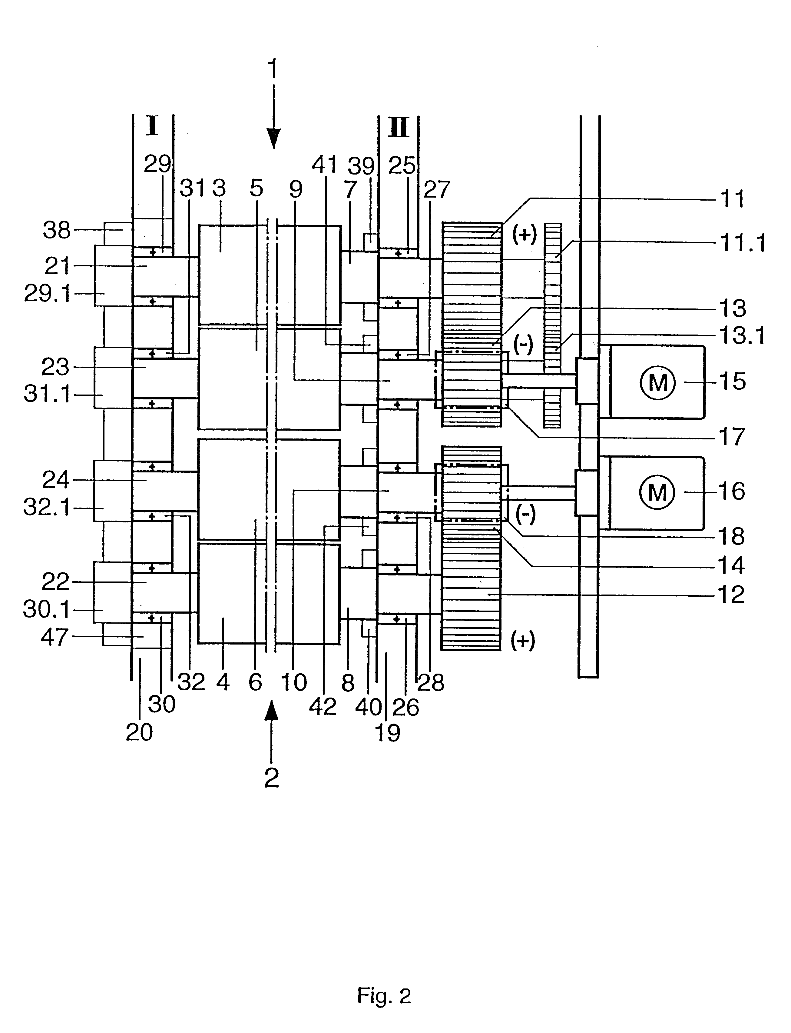
The double printing unit shown in FIGS. 1 and 2 contains the two printing units 1, 2, each having a form cylinder 3, 4 and each having a transfer cylinder 5, 6. The form and transfer cylinders 3 to 6, also referred to as printing-unit cylinders in the following text, each bear a spur gear 11 to 14 on their drive-side journals 7 to 10, with which the form cylinder 3, 5 and the transfer cylinder 4, 6 of a printing unit 1, 2 in each case have a drive connection (FIG. 2). On the other hand, the transfer cylinders 5, 6 do not have a drive connection via their spur gears 13, 14. For this purpose, the spur gears 13, 14 are provided with an appropriate negative profile displacement. In order to maintain the required engagement relationships with the predefined axle spacings of the form and transfer cylinders 3, 5 and 4, 6, respectively, the spur gears 11, 12 have a positive profile displacement. If the profile displacements were to be dispensed with, the spur gears 11, 13 of the printing un...


PUM


Abstract

Large throw-off distances of the transfer cylinders in a double printing unit of a rotary printing machine operating on the rubber/rubber principle are achieved by enabling the two transfer cylinders to be set away from each other, and enabling the two form cylinders to be set away from the respective transfer cylinder. The form cylinder and the transfer cylinder of each printing unit have a drive connection via spur gears, the transfer cylinders are not in tooth engagement via their spur gears, and each printing unit has its own electric motor.

Description

1. Field of the InventionThe invention relates printing machines, and more particularly, to a double printing unit of a rotary printing machine which can be switched off for a rapid production change, while the web continues to be led through between the transfer cylinders which have been moved out of contact.2. Description of the Related ArtDE 93 11 113 U1 shows a double printing unit serving as a single printing unit, in which the form and transfer cylinders are arranged one above another. All four printing-unit cylinders have a drive connection to spur gears located on their journals. The drive is provided by means of a main shaft via a bevel-gear mechanism and an intermediate gear on one of the spur gears of the transfer cylinders. This drive can be disengaged by means of a clutch when the double printing unit is switched off for a plate change needed in the event of a production change. In order to put the drive back into service, the double printing unit is accelerated by mean...

Claims


Application Information

Patent Timeline
Patent Type & Authority Patents(United States)
IPC IPC(8): B41F13/24B41F7/12B41F13/28B41F7/00
CPCB41F7/12B41F13/24B41F13/28B41F13/32B41P2213/734
Inventor KNAUER, PETERSINGLER, JOSEF
Owner MANROLAND WEB SYST
Why Eureka
Try Eureka