Quilt clamp

Inactive Publication Date: 2001-05-01
HINDSLEY LORA L
View PDF12 Cites 14 Cited by
  • Summary
  • Abstract
  • Description
  • Claims
  • Application Information

AI Technical Summary

Problems solved by technology

This can be difficult when the quilter has only an inch or so of quilting material to grasp or whe

Method used


Image

  • Quilt clamp
  • Quilt clamp
  • Quilt clamp

Examples


Embodiment Construction

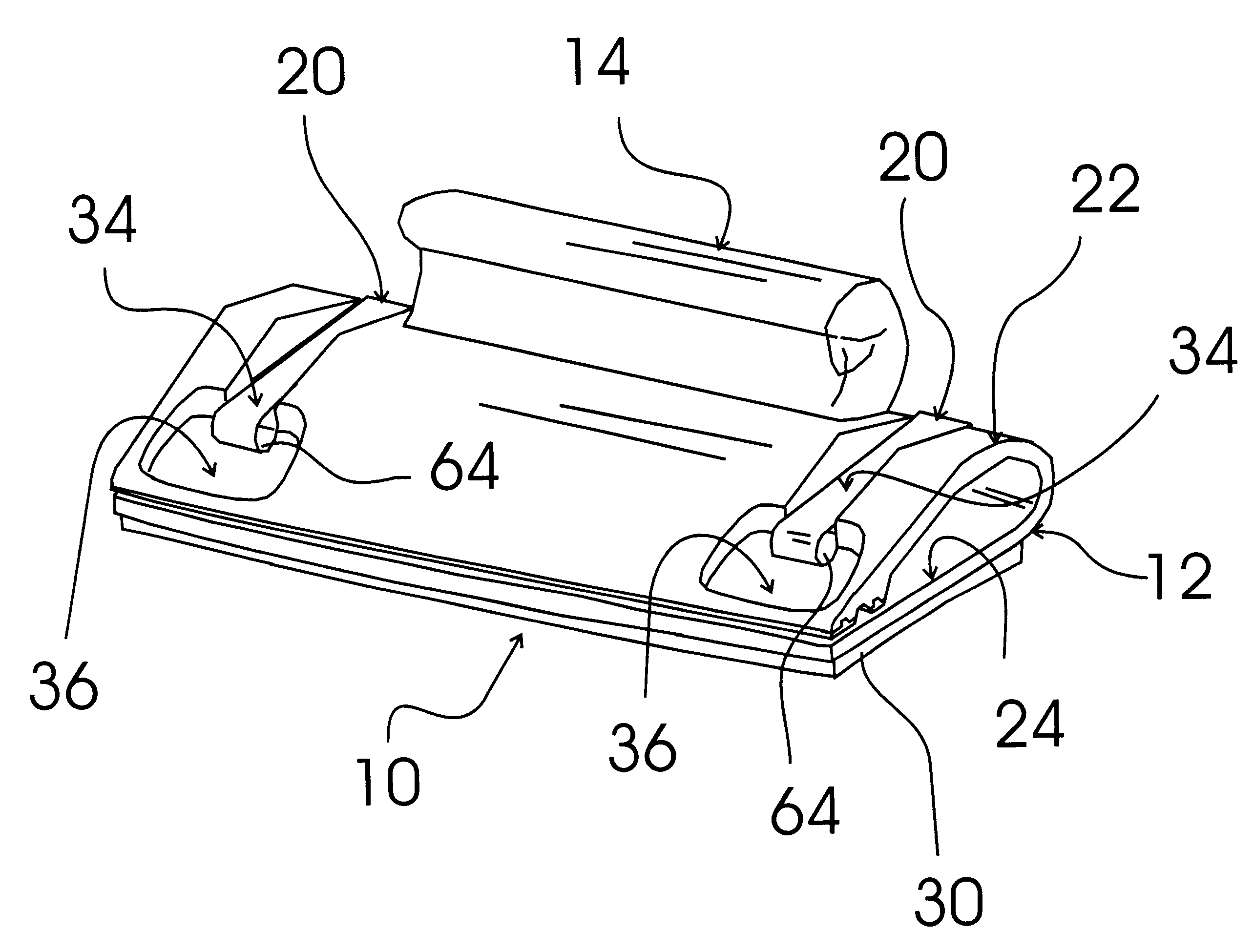
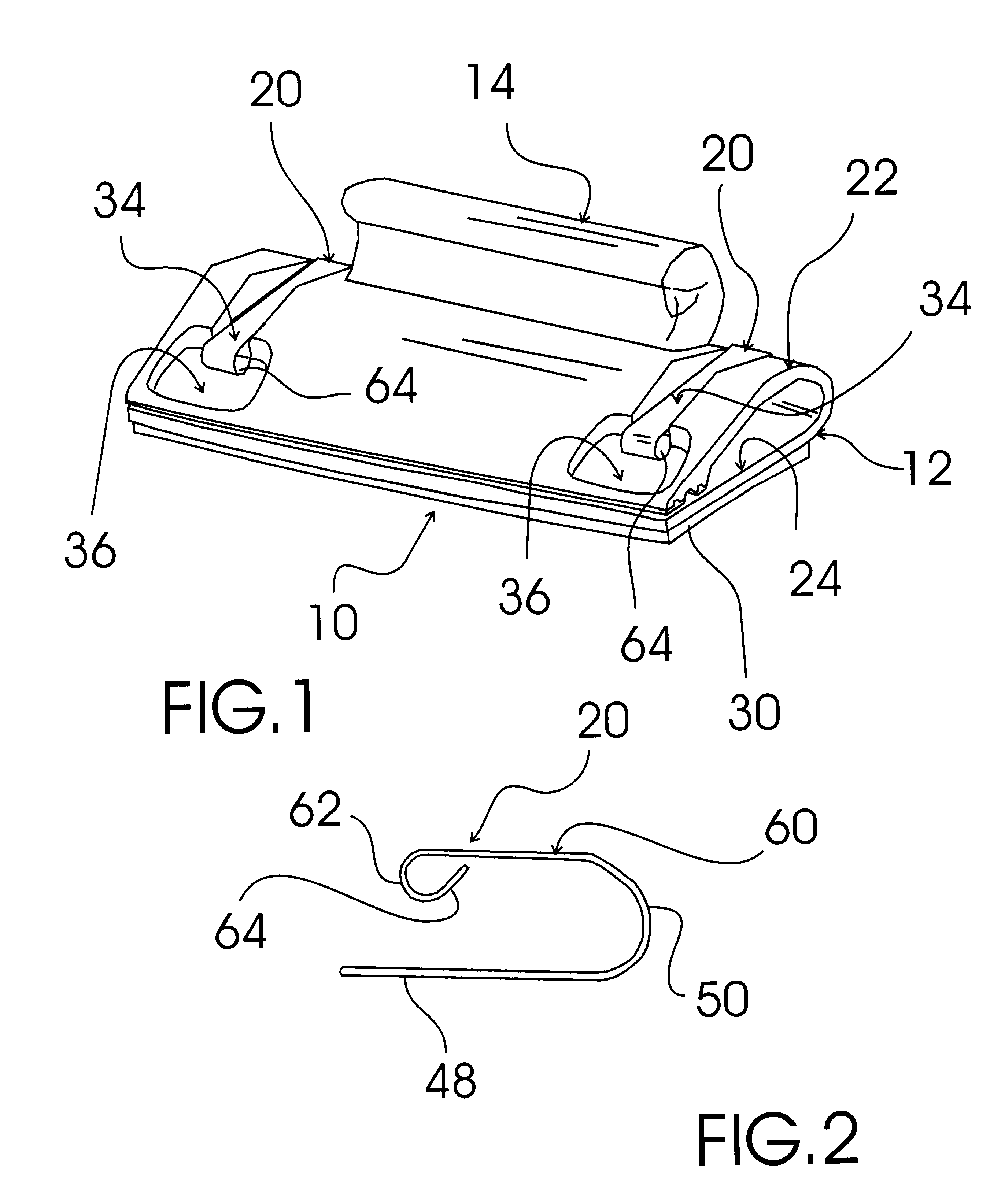
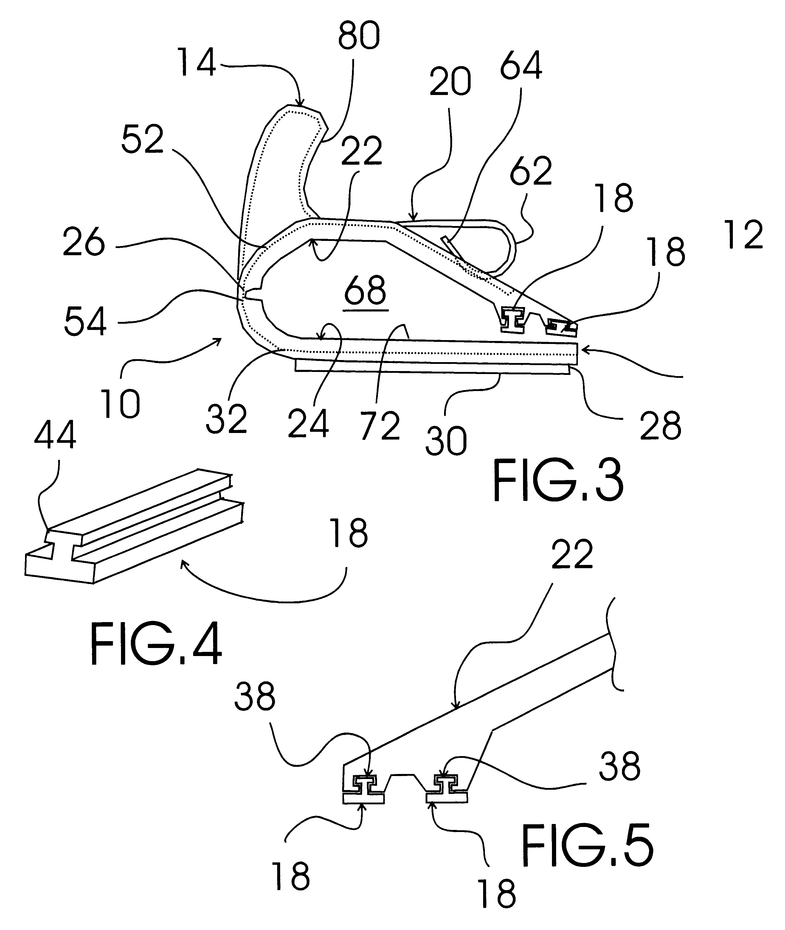
FIGS. 1-6 show various aspects of an exemplary quilt clamp of the present invention generally designated 10. Quilt clamp 10 includes a plastic clamp body, generally designated 12; a clamp handle, generally designated 14; two spaced resilient clamping teeth, each generally designated 18; and two clamp springs, each generally designated 20.

Plastic clamp body 12 is of molded plastic construction and includes a top clamp portion, generally designated 22, integrally formed with and hingedly connected to a bottom clamp portion, generally designated 24, with a flexible plastic hinge portion 26. Bottom clamp portion 24 has a bottom surface 28 covered with felt material 30 and two spaced bottom clamp spring receiving channels 32 (shown in dashed lines FIG. 3) formed between bottom surface 28 and felt material 30. Felt material 30 is provided to allow quilting clamp 10 to slide easily on quilting tables and sewing machine tops.

Top clamp portion 22 has two spaced clamp spring guide channels, g...


PUM

PropertyMeasurementUnit
Lengthaaaaaaaaaa
Flexibilityaaaaaaaaaa

Abstract

A clamp for use in quilting that includes a top and a bottom quilt clamp portion that are forced together by a pair of springs to hold multiple layer of quilting materials, such as fabric and batting, firmly together while stitching the quilt pattern. To facilitate movement of the multiple layers in the desired quilt pattern, the quilt clamp is provided with a handle. The bottom surface of the quilt clamp is covered with felt to enhance the slidableness of the clamp on quilting tables and sewing machines.

Description

The present invention relates to sewing accessories and more particularly to a quilt clamp for securely clamping and holding multiple layers of material together for quilting that includes a plastic clamp body, a clamp handle, two spaced resilient clamping teeth, and two clamp springs; the plastic clamp body including a top clamp portion integrally formed with and hingedly connected to a bottom clamp portion with a flexible plastic hinge portion; the bottom clamp portion having a bottom surface covered with a felt material and two spaced bottom clamp spring receiving channels formed between the bottom surface and the felt material; the top clamp portion having two spaced clamp spring guide channels each terminating in a clamp spring end portion receiving depression, two spaced clamping teeth attachment channels each having a T-shaped channel running the length of the top clamp portion for receiving a T-shaped channel insertion portion of one of the two resilient clamping teeth; each...

Claims


Application Information

Patent Timeline
IPC IPC(8): D05B35/00D05B35/10D05C1/00D05B39/00D05C1/02
CPCD05B35/105D05B39/005D05C1/02
Inventor HINDSLEY, LORA L.
Owner HINDSLEY LORA L
Why Eureka
Try Eureka