Low profile highly expandable stent

a high-expansion, low-profile technology, applied in the field of stents, can solve the problems of increasing the risk of patients, reducing the degree of expansion of the stent, and limiting the degree of expansion of the prior-art stent,

Inactive Publication Date: 2001-05-01
VASCULAR CONCEPTS HLDG
View PDF16 Cites 104 Cited by
  • Summary
  • Abstract
  • Description
  • Claims
  • Application Information

AI Technical Summary

Problems solved by technology

Unfortunately, the degree of expansion of the '892 stent is determined by the balloon used to expand the stent or the elastic nature of the metal used on the rigid parts.
Such prior art stents are very limited in their degree of expansion and are not capable of the high degree of expansion seen in the

Method used


Image

  • Low profile highly expandable stent
  • Low profile highly expandable stent
  • Low profile highly expandable stent

Examples


Embodiment Construction

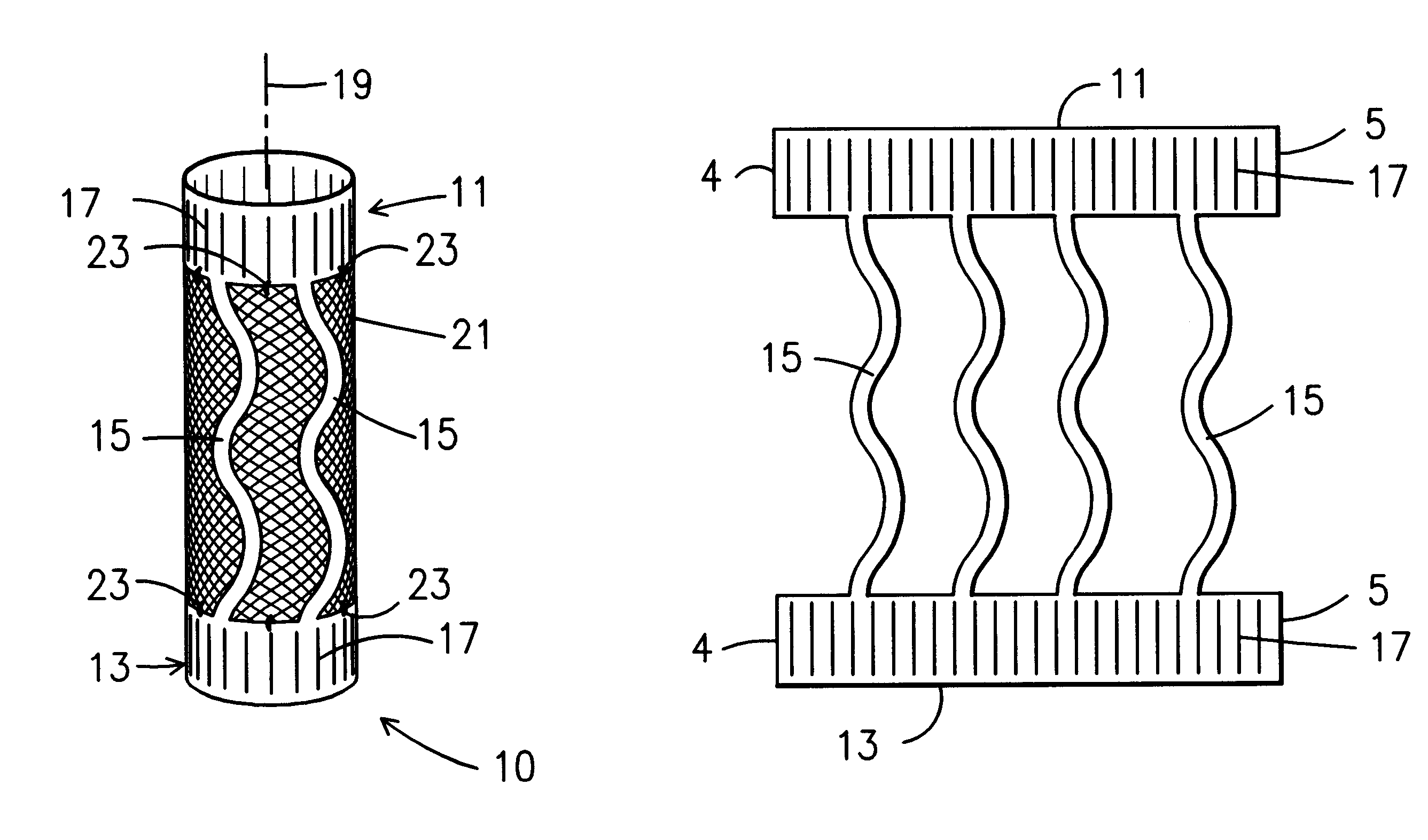
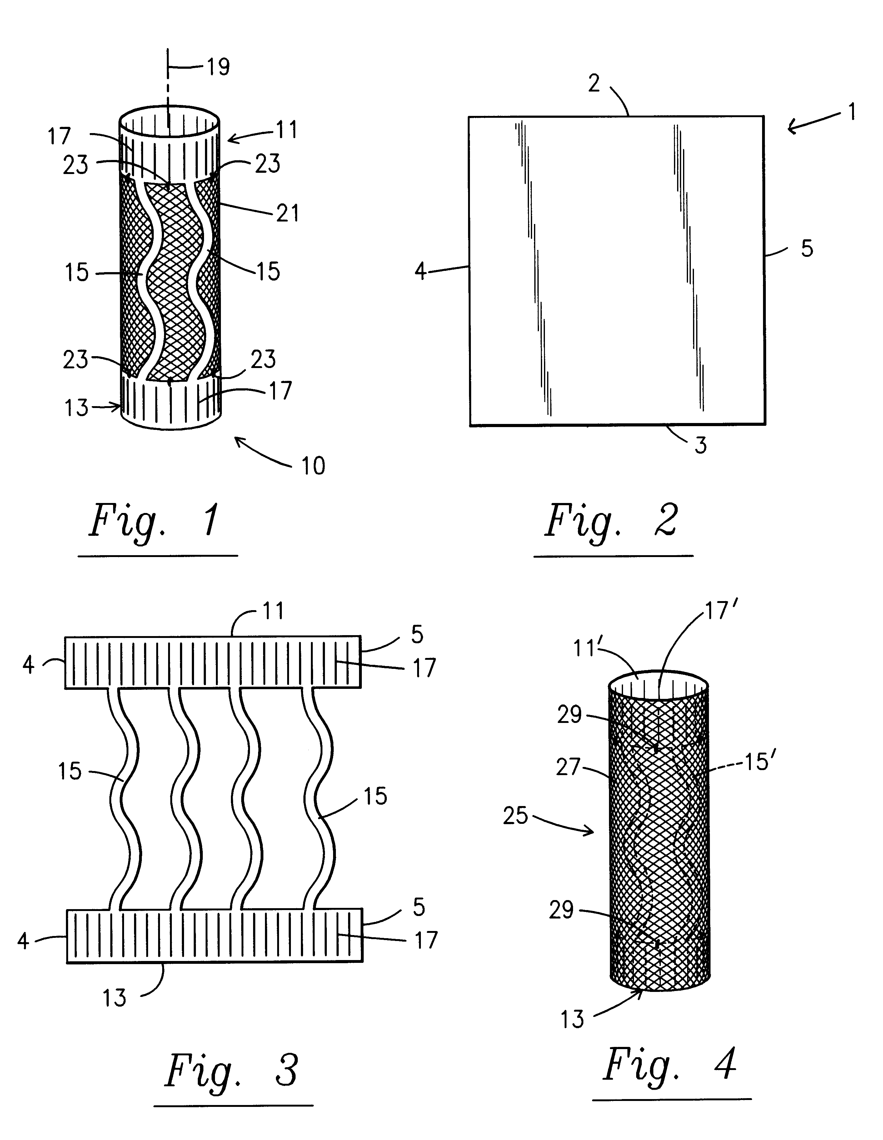
With reference, first, to FIG. 1, a first embodiment of the present invention is generally designated by the reference numeral 10 and is seen to include a framework consisting of end pieces 11 and 13 interconnected with connecting pieces 15. The end pieces 11 and 13 have spaced slits 17 that allow radial expansion. In the preferred embodiment, slits 17 are formed by cutting the material that form end pieces 11 and 13. The connecting pieces 15 are serpentine in configuration allowing longitudinal expansion along the axis 19 of elongation of the stent 10.

FIG. 2 depicts a piece 1 of NITINOL material that is generally rectangular including ends 2, 3 and side edges 4 and 5. With reference to FIG. 3, it is seen that the sheet 1 of NITINOL material may be cut with any suitable cutting means to form the structure shown in FIG. 3. The structure shown in FIG. 3 includes the end pieces 11 and 13 as well as the connecting pieces 15 before the end pieces 11 and 13 have been rolled into the cylin...


PUM


Abstract

A stent is disclosed in several embodiments including the use of a material known as NITINOL forming the ends of the stent as well as support structure connecting the ends. A fabric is interconnected with the NITINOL structure to form the stent. The NITINOL material ends have slits parallel with the direction of elongation of the stent allowing radial expansion of the ends. The pieces interconnecting the ends have a serpentine shape allowing longitudinal expansion of the stent. The NITINOL material structure may be located within the fabric portion or outside the fabric portion. The connecting pieces may be separate structures attached to the fabric. Alternatively, the end pieces may be separate structures attached to the fabric without the connecting pieces.

Description

1. Field of the InventionThe present invention relates to a stent. More particularly, it relates a low profile highly expandable stent.2. Description of the Prior ArtStents for use in transluminal implantation are known in the prior art. Most are known to be balloon expandable, self-expandable, or thermally expandable. But, the degree of expansion in these prior art stents are determined by the diameter of the balloon used to cause the expansion or of the diameter of an artery when using self-expanding or thermally expanding means. An improved stent is needed in which the degree of expansion in the stent is not constrained by diameter of the balloon or of the artery.Some prior art stents are known to comprise rigid and flexible portions. U.S. Pat. No. 5,383,892 ('892) to Cardon et al. disclose a stent employing at least two cylindrical rigid parts and at least one flexible part where the flexible part is welded to the rigid parts. Such a stent could be considered a combination stent...

Claims


Application Information

Patent Timeline
IPC IPC(8): A61F2/06A61F2/90
CPCA61F2/07A61F2/90A61F2002/075A61F2/89A61F2220/0075
Inventor JAYARAMAN, SWAMINATHAN
Owner VASCULAR CONCEPTS HLDG
Why Eureka
Try Eureka