Diaphragm valve

a technology of diaphragm valve and valve stop, which is applied in the direction of diaphragm valve, engine diaphragm, operating means/release devices of valves, etc., can solve the problems of premature failure and leakage through the valve, difficulty in adjusting the position of such a valve stop, and damage to the diaphragm of elastomeric or plastic diaphragm

Inactive Publication Date: 2001-06-05
ITT MFG ENTERPRISES LLC
View PDF5 Cites 34 Cited by
  • Summary
  • Abstract
  • Description
  • Claims
  • Application Information

AI Technical Summary

Problems solved by technology

It is also well known manually actuated valves provided with elastomeric or plastic diaphragms may experience damage to the diaphragm during closing.
During closing, the diaphragm may be exposed to high closing forces, ultimately resulting in premature failure and leakage through the valve.
A shortcoming of this approach lies in the difficulty of adjusting the position of such a valve stop.
This typically requires a technician using at least three separate tools at great time and expense.
As is well known though, there are a number of reasons which may prevent the valve from fully closing, and such a configuration undesirably requires fully removing the handwheel and cap to fully close the valve in such an instance.

Method used


Image

  • Diaphragm valve
  • Diaphragm valve

Examples


Embodiment Construction

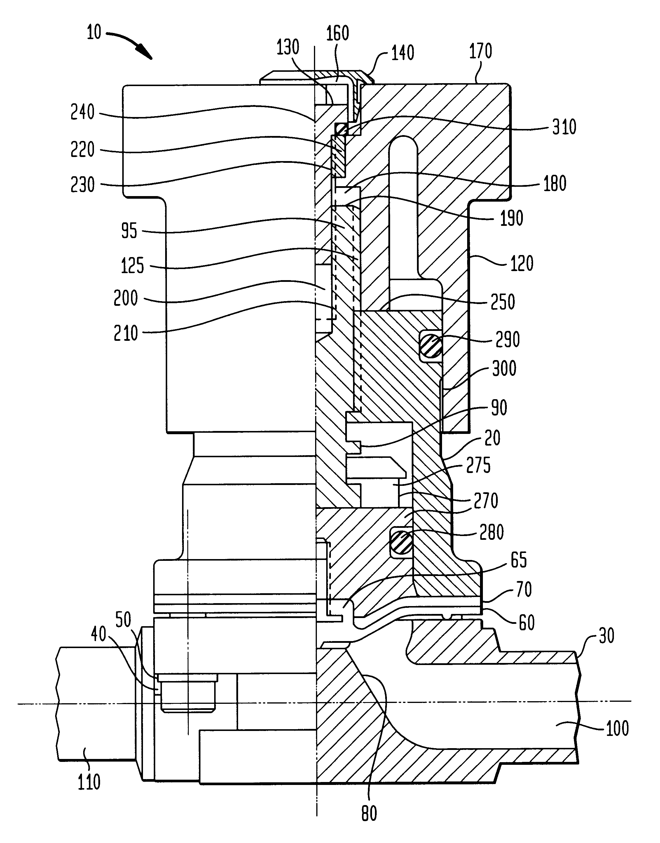
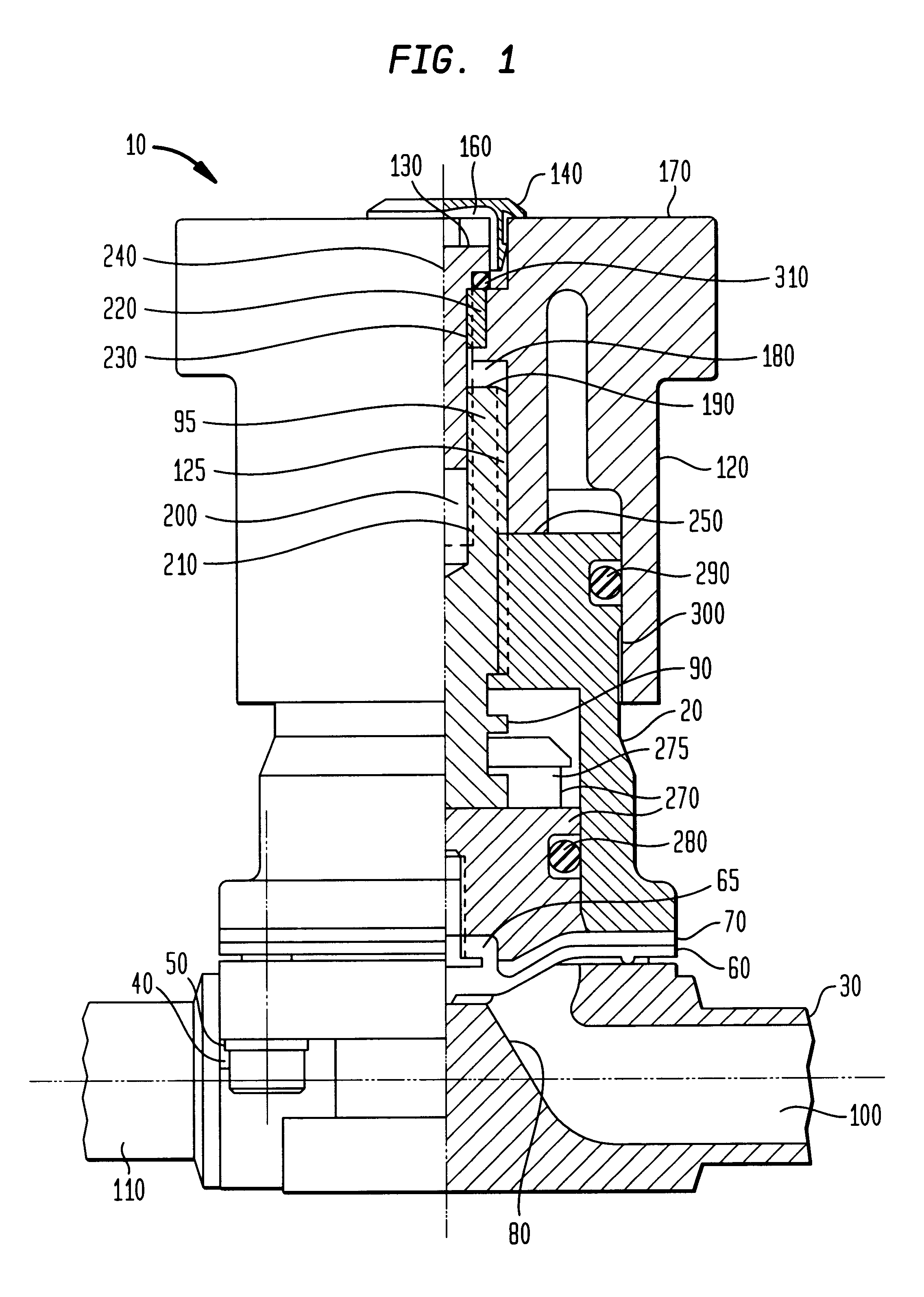
Referring now to FIG. 1, there is illustrated a partial cross-section of a preferred embodiment of the diaphragm valve 10 according to the present invention. The valve 10 includes bonnet 20 secured to body 30 by bolts 40 and washers 50. Diaphragm 60 and cushion backing 70 are secured between the body 30 and bonnet 20, and are adapted to be deflected against weir 80 to obstruct flow between ports 100 and 110 by the stem 90 bearing against the compressor 270. The diaphragm 60 includes a portion 65 threaded into the compressor 270. The compressor has a T-slot 275 milled into it, which the stem 90 slides into during assembly, longitudinally securing the stem 90 to the compressor 270. Thus, as the stem 90 is displaced towards or away from the weir 80, the compressor 270 is correspondingly displaced. As will be understood by those possessing ordinary skill in the pertinent art, the compressor 270 and stem 90 T-slot 275 connection is important as it permits the stem 90 to be rotatable with...


PUM


Abstract

A valve including: a bonnet; a body secured to the bonnet and including at least two ports and at least one weir positioned between the ports; a valve stem being movably coupled with the bonnet, the valve stem including first and second longitudinal ends, and a recess in the first longitudinal end; a diaphragm positioned substantially adjacent to the second end of the valve stem so as to be deflectable towards the weir by the valve stem to restrict a flow between the ports; a handwheel rotatably secured to the valve stem so as to enable a torque to be applied to the valve stem, the handwheel including a longitudinal aperture; and, a screw directed through and engaged with the handwheel aperture and being selectively engagable within the recess of the valve stem, such that the valve stem and handwheel remain in a constant relative longitudinal position with respect to one another, and when the diaphragm sets against the weir the handwheel abuts the bonnet to serve as a closing lift valve stop.

Description

The present invention relates generally to diaphragm valves, and more particularly to diaphragm valves being manually operable by a handwheel to actuate a diaphragm by the use of a rotatable valve stem.BACKGROUND OF INVENTIONDiaphragm valves selectively operable to restrict or permit fluid flow are generally well known in the art. Such valves conventionally include a weir or valve seat. An elastomeric or plastic diaphragm can be set against and removed from the valve seat responsively to rotation of a valve stem. The valve stem serves to transfer forces which in turn deflect the diaphragm and hence open and close the valve. A handwheel is typically rotatably coupled to the valve stem for exerting rotational forces to the valve stem sufficient to deflect the diaphragm. It is also well known manually actuated valves provided with elastomeric or plastic diaphragms may experience damage to the diaphragm during closing. During closing, the diaphragm may be exposed to high closing forces,...

Claims


Application Information

Patent Timeline
Patent Type & Authority Patents(United States)
IPC IPC(8): F16K7/12F16K7/16F16K31/50
CPCF16K7/126
Inventor BUTLER, RONALD G.
Owner ITT MFG ENTERPRISES LLC
Why Eureka
Try Eureka