Orthodontic device

Inactive Publication Date: 2001-06-05
TOMY CHOFU TOKIOTOKYO JP
View PDF3 Cites 23 Cited by
  • Summary
  • Abstract
  • Description
  • Claims
  • Application Information

AI Technical Summary

Problems solved by technology

On the other hand, in order to make the buccal tube, separate components have to be assembled by brazing and this not only lowers the efficiency of construction but also causes the disadvantage that the materials of the respective components may be embrittled by the heat of brazing.
Consequently, this makes it impossible to adjust the value of IN / OUT H to 0.3 mm according to the orthodontist's requirement.
On the other hand, the width of the weld flange 12 in an occluso-gingival direction is adapted to be the same as the width of the rectangular tube body 11 in the same direction and this presents a serious problem when the flange 12 is welded to the band.
Needless to say, great difficulty is encountered with the welding procedure if the weld flange 12 is narrow.
However, if the weld flange 12 is unduly long, the buccal tube no longer conforms to the shape of the band 14.
However, if the rectangular tube body 11 is broadened together with the weld flange 12, it may then have occlusive interference with antagonistic teeth on the occlusion side or it may contact the gingiva on the gingival side to cause its potential swelling.
As a further problem, brushing is difficult to perform and this is not desirable to oral hygiene.
Further, food debris remaining under the hook 13 is difficult to brush off, again causing a problem in oral hygiene.

Method used


Image

  • Orthodontic device
  • Orthodontic device
  • Orthodontic device

Examples


Embodiment Construction

The present invention is described below in detail with reference to the preferred embodiments shown in accompanying drawings.

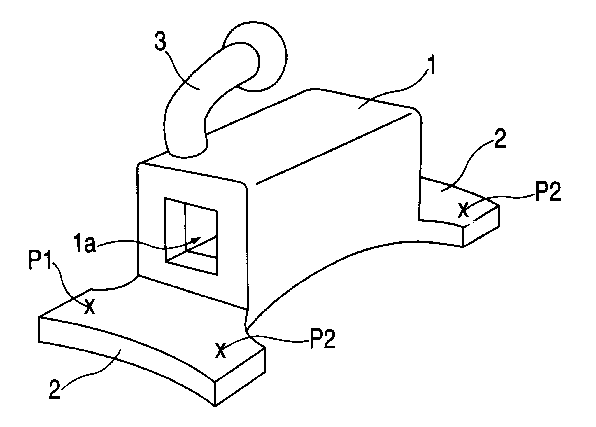
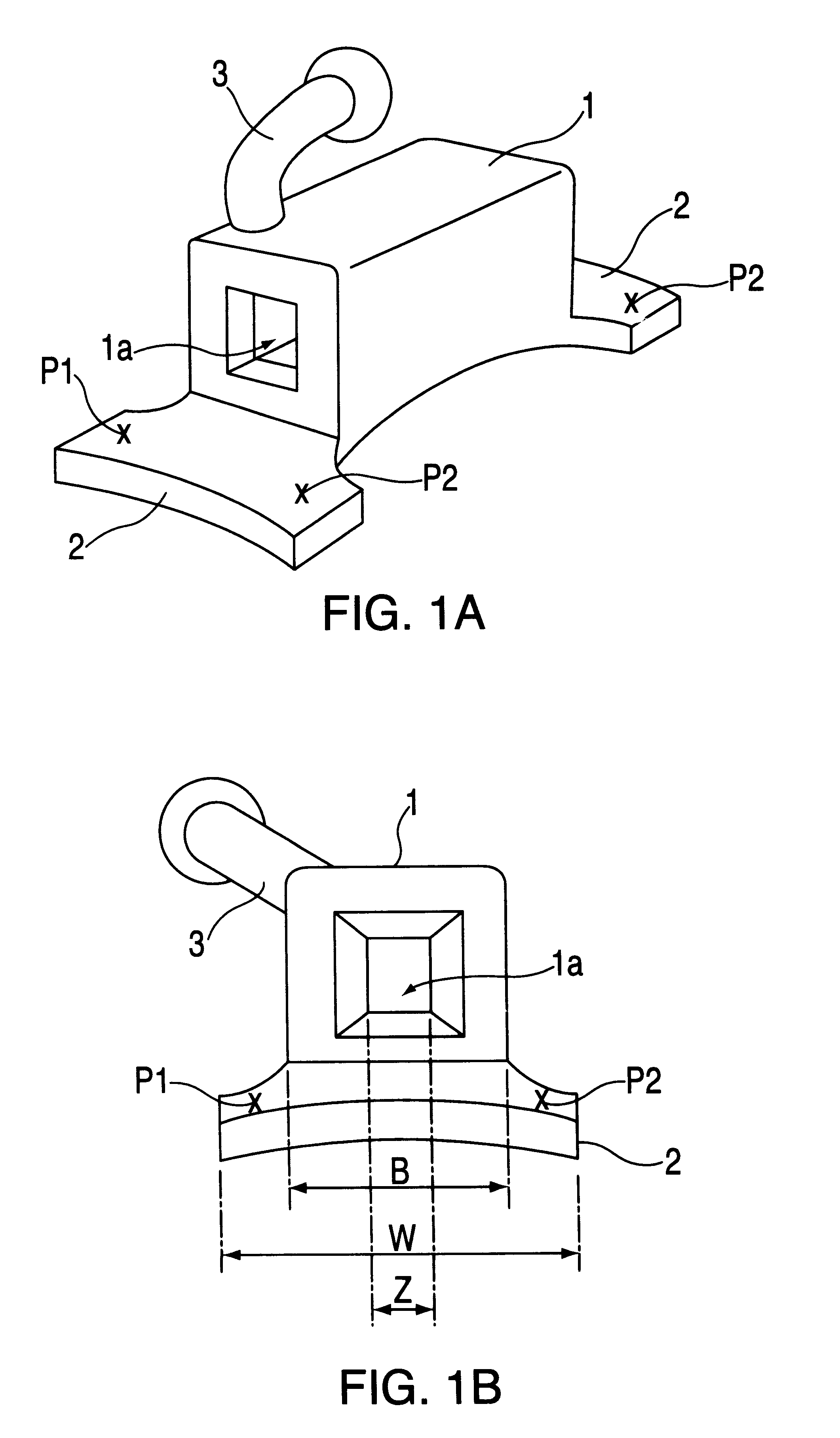
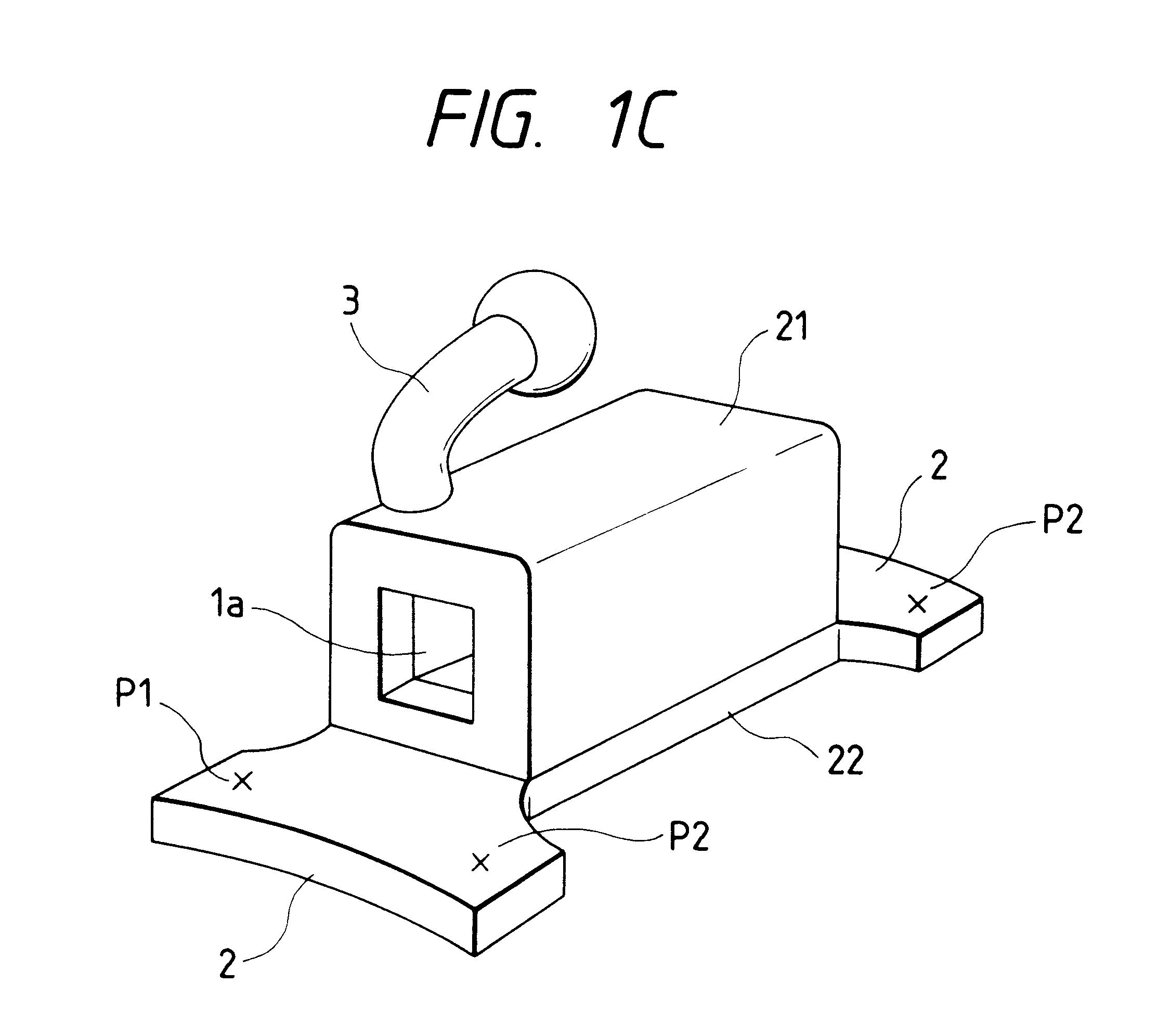
The orthodontic device according to the preferred embodiment of the present invention is a buccal tube of the integral molding type (one-piece type). As shown in FIGS. 1A and 1B, the buccal tube consists of a rectangular tube body 1, a pair of weld flanges 2 and a hook 3. The rectangular tube body 1 has a through-hole la serving as an opening through which an end of an arch wire serving as a principal wire is detachably passed in a mesiodistal direction. The pair of weld flanges 2 extend in the mesiodistal direction of the rectangular tube body 1. The hook 3 engages an elastic wire (thread or chain) or a ligature wire. The buccal tube shown in FIGS. 1A, 1B and 1C has the features of the construction described below. Incidentally, as shown in FIG. 2A, the through-hole la may be of such a type that a groove becomes exposed upon removal of a convertible cap or o...


PUM


Abstract

In an orthodontic device, a main body (1) has an opening (1a) formed to permit detachable passage of a principal wire and a flange (2) formed in a mesiodistal direction so that the device is fixed via said extension flange (2) to an band to be fitted over the crown of molar. The width (W) of the extension flange (2) in an occluso-gingival direction is made greater than the width (B) of said main body (1) in the same direction.

Description

1. Field of InventionThe present invention relates an improvement of an orthodontic device in the orthodontic treatment, specifically, to an orthodontic device, which is welded to a band, such as a buccal tube, a lingual sheath, a lingual tube and the like.2. Description of the Related ArtFor orthodontic treatment, brackets retaining an arch wire are fixed on the surfaces of the patient's teeth and the elastic recovery of the arch wire is applied to the teeth via the bracket. The bracket is used with a buccal tube which is fitted over the molars of the patient with the aid of a band and its principal purpose is to retain the ends of the arch wire. As shown in FIGS. 3A and 3B, the buccal tube has a broad weld flange 12. A rectangular tube body 11 and a hook 13 are brazed to the top surface of the broad weld flange 12. The tube body 11 has a through-hole 11a through which an end of the arch wire is detachably passed in a mesiodistal direction. The hook 13 is used to engage an elastic ...

Claims


Application Information

Patent Timeline
IPC IPC(8): A61C7/00A61C7/28A61C7/20
CPCA61C7/282
Inventor ORIKASA, MASAAKIWATANABE, YASUSHI
Owner TOMY CHOFU TOKIOTOKYO JP
Why Eureka
Try Eureka