
Check valve for a piston pump in a fluid circulation system

a fluid circulation system and check valve technology, applied in the direction of valve housings, braking systems, liquid fuel engines, etc., can solve the problem of relatively complicated geometries

Inactive Publication Date: 2001-06-12
ROBERT BOSCH GMBH
View PDF18 Cites 95 Cited by
  • Summary
  • Abstract
  • Description
  • Claims
  • Application Information

AI Technical Summary

Problems solved by technology

The closure element is a part that is geometrically relatively complicated, with a radial flange by which it is mounted in the valve housing, and with a tube segment or truncated cone, protruding integrally from the radial flange into the interior of the valve housing, that serves as a stop for the valve closing body and forms a valve stroke limitation.

Method used


Image

  • Check valve for a piston pump in a fluid circulation system
  • Check valve for a piston pump in a fluid circulation system
  • Check valve for a piston pump in a fluid circulation system

Examples


Embodiment Construction

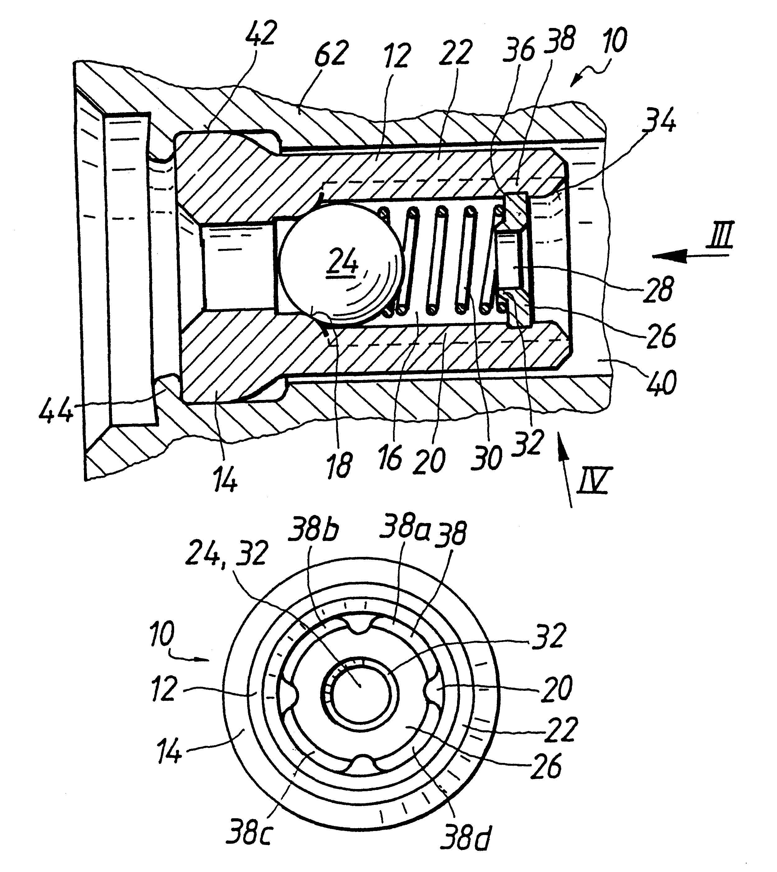
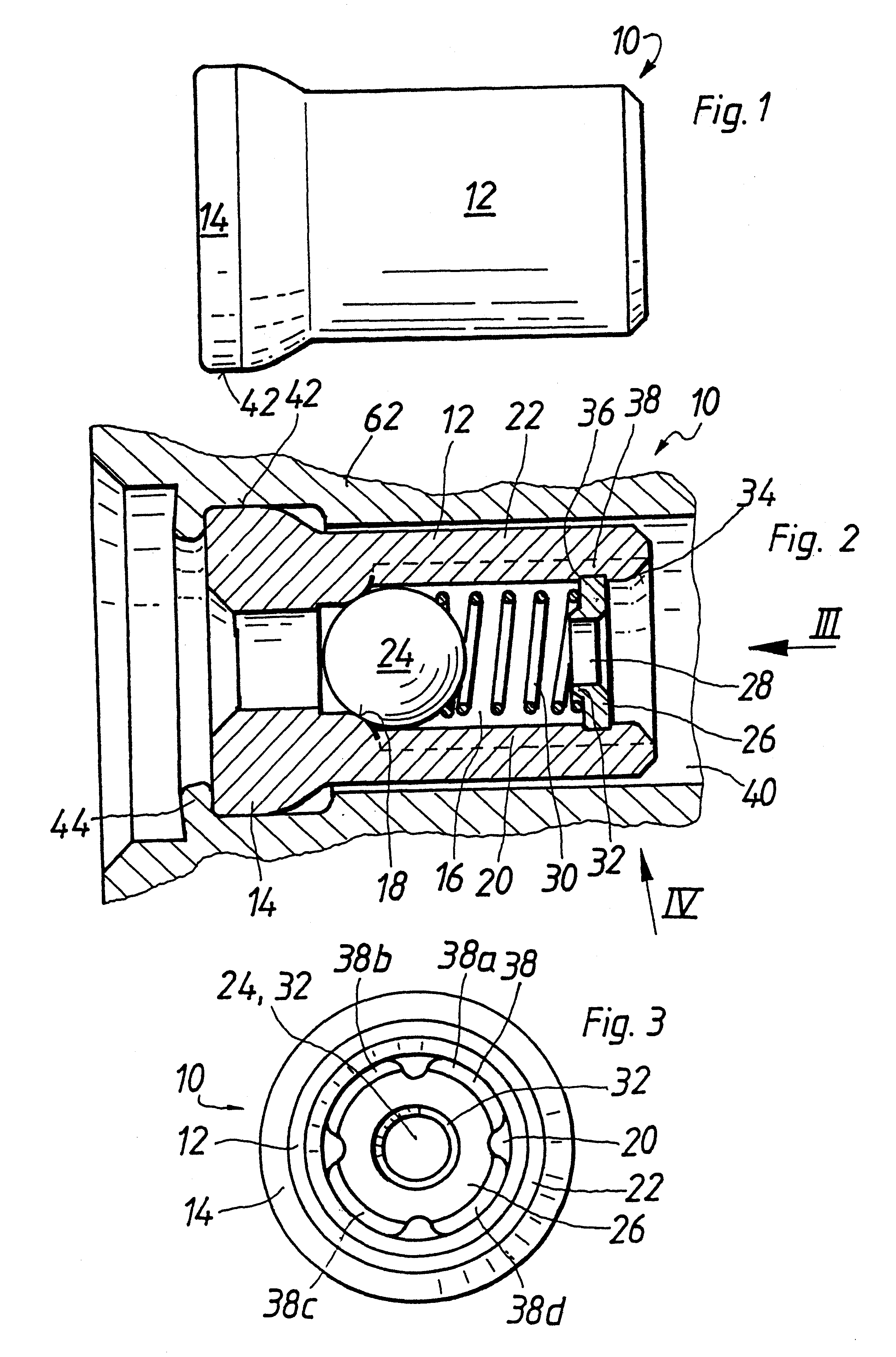
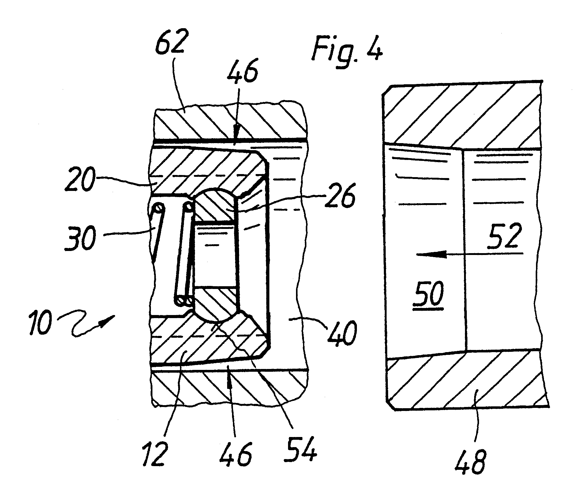
The check valve 10 of the invention, shown in FIGS. 1-3, has a valve housing 12 with a radially protruding sealing collar 14 extending all the way around on an inflow end. For reasons of space and to attain high stability while using little material, the preferably selected valve housing shown in the drawing is tubular in design.

An axial through bore 16 widens in a flow direction at an encompassing annular shoulder, which forms a valve seat 18. In the preferably selected exemplary embodiment, the valve seat 18 is embodied as crowned in convex fashion, but can also be frustoconical, for instance. Extending away from the valve seat 18 in the flow direction, that is, toward an outflow end of the check valve 10, the valve housing 12 has a plurality of guide ribs 20, preferably from 3 to 6 and in particular four of them, which protrude radially inward from an inside of a circumferential wall 22 of a valve housing 12. The guide ribs 20 are preferably distributed equidistantly over the cir...


PUM


Abstract

The invention relates to a check valve with a tubular valve housing in which a valve ball is received. To make a large flow cross section available and to prevent closure by the valve ball when the check valve is fully open, a perforated disk is press-fitted between longitudinally extending guide ribs of the valve housing and a circumferential wall of the valve housing there is an interstice as an outflow opening, which is not closed even the valve ball contacts the perforated disk. The valve housing is made by stamping, in which the guide ribs and a valve seat are made in one operation and are thereby aligned exactly with one another. In this way, a small radial play of the valve ball can be realized.

Description

PRIOR ARTThe invention is based on a check valve for an oil circulation system.One such check valve, intended especially for an oil circulation system in an internal combustion engine, is known from European Patent Disclosure EP 0 268 520 B1. The known check valve has a tubular valve housing, on one end of which a valve seat is formed and in whose other end a closure element is inserted that between itself and the valve seat encloses a valve closing body in the form of a valve ball received in the valve housing. The closure element is a part that is geometrically relatively complicated, with a radial flange by which it is mounted in the valve housing, and with a tube segment or truncated cone, protruding integrally from the radial flange into the interior of the valve housing, that serves as a stop for the valve closing body and forms a valve stroke limitation.ADVANTAGES OF THE INVENTIONThe valve housing of the check valve of the invention, has inward-protruding guide ribs for guidi...

Claims


Application Information

Patent Timeline
IPC IPC(8): B60T8/40B60T8/34F16K27/02F16K15/04F16K15/02F04B53/10
CPCB60T8/341B60T8/4031F16K15/021F16K15/023F16K15/026F16K15/028F16K15/044F16K27/0245F16K27/029Y10T137/7929Y10T137/7927F16K15/02
Inventor BARTUSSEK, WALTERHEUSINKVELD, JOERGHUEBER, HUBERTRITTLER, WERNERHAECKER, JUERGENOTT, HARALDAICHER, HARALD
Owner ROBERT BOSCH GMBH
Learn More