Slide rail for removable vehicle seat

a vehicle seat and slide rail technology, which is applied in the direction of roofs, chairs, safety belts, etc., can solve the problems of inability to be damaged by the passengers of the vehicle, conceivable electrically, and less functionality than non-removable seats

Inactive Publication Date: 2001-07-31
BERTRAND FAURE EQUIP SA (FR)
View PDF27 Cites 64 Cited by
  • Summary
  • Abstract
  • Description
  • Claims
  • Application Information

AI Technical Summary

Benefits of technology

As a result of these features, the flexible electrical cabling remains permanently hidden under the upper flange of the fixed section, so that this cabling does not hinder the users of the vehicle and does not risk being damaged by them when the seat is removed or moved in order to free the floor.

Problems solved by technology

Because the seats carried by these slide rails are removable, it is not conceivable to electrically supply these seats by means of a cable layer or of a bundle of cables left free on the vehicle floor under the seat part of the seat, as is the case for non-removable seats.
Indeed, this layer or this bundle of cables would be in the way and would be able to be damaged by the passengers of the vehicle when the seat frees the floor zone normally situated under it.
Removable seats of this type do not therefore generally include any electrical equipment, so that they have less functionality than non-removable seats.

Method used


Image

  • Slide rail for removable vehicle seat
  • Slide rail for removable vehicle seat
  • Slide rail for removable vehicle seat

Examples


second embodiment

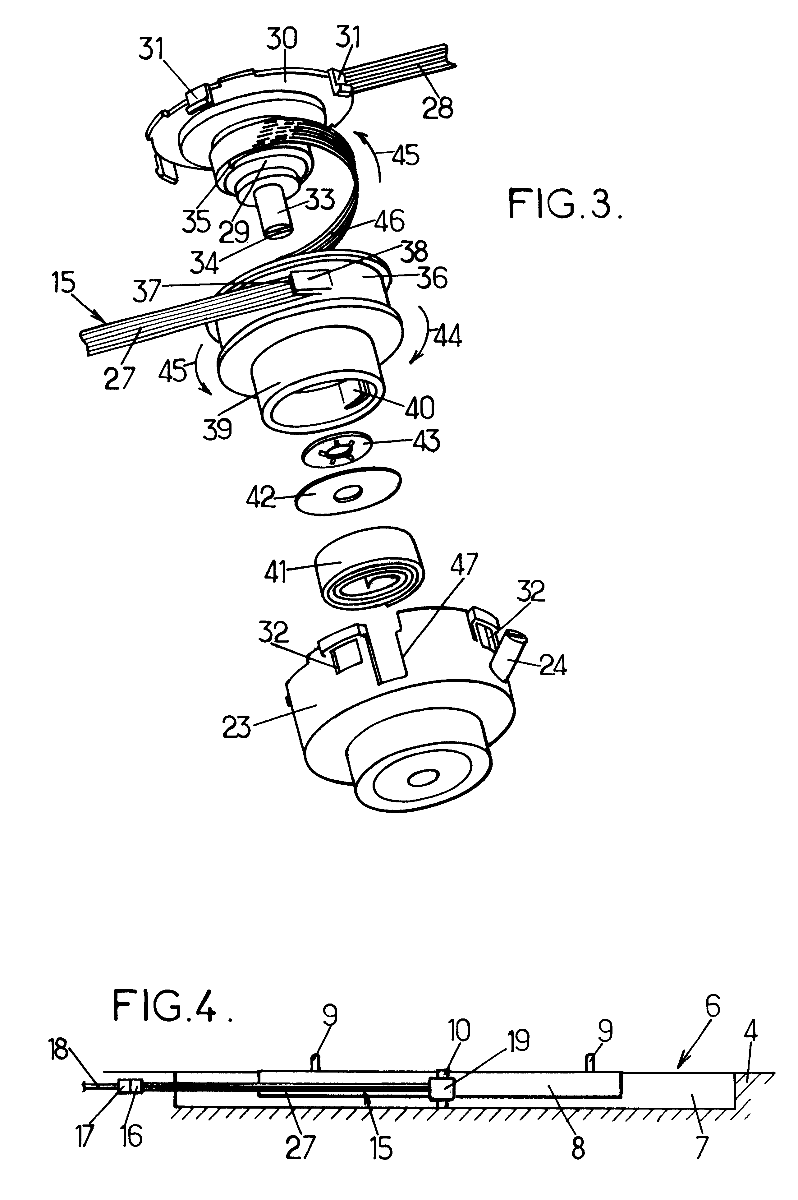
the invention, which is shown in FIG. 4, is very similar to the embodiment described above, and will not therefore be described again in detail here.

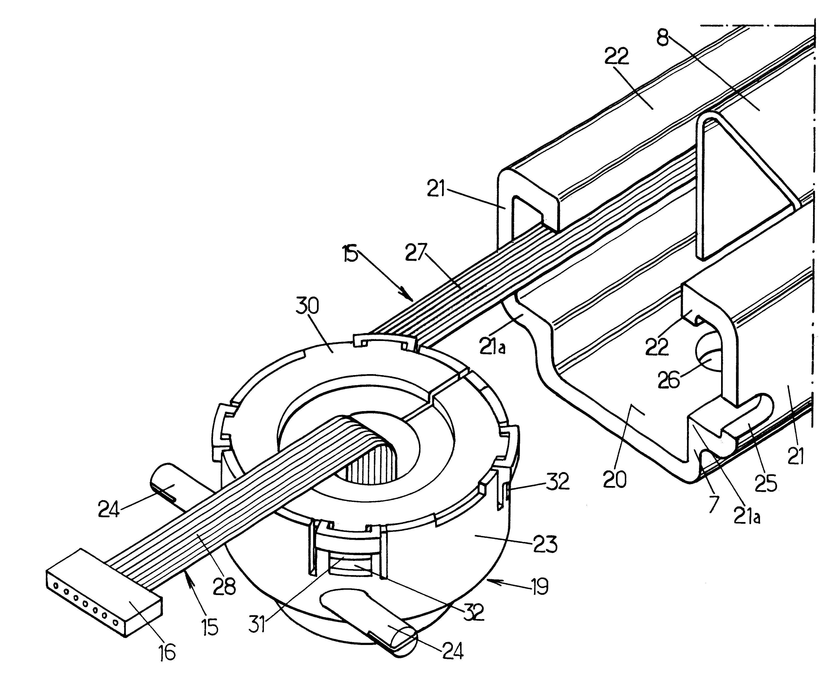
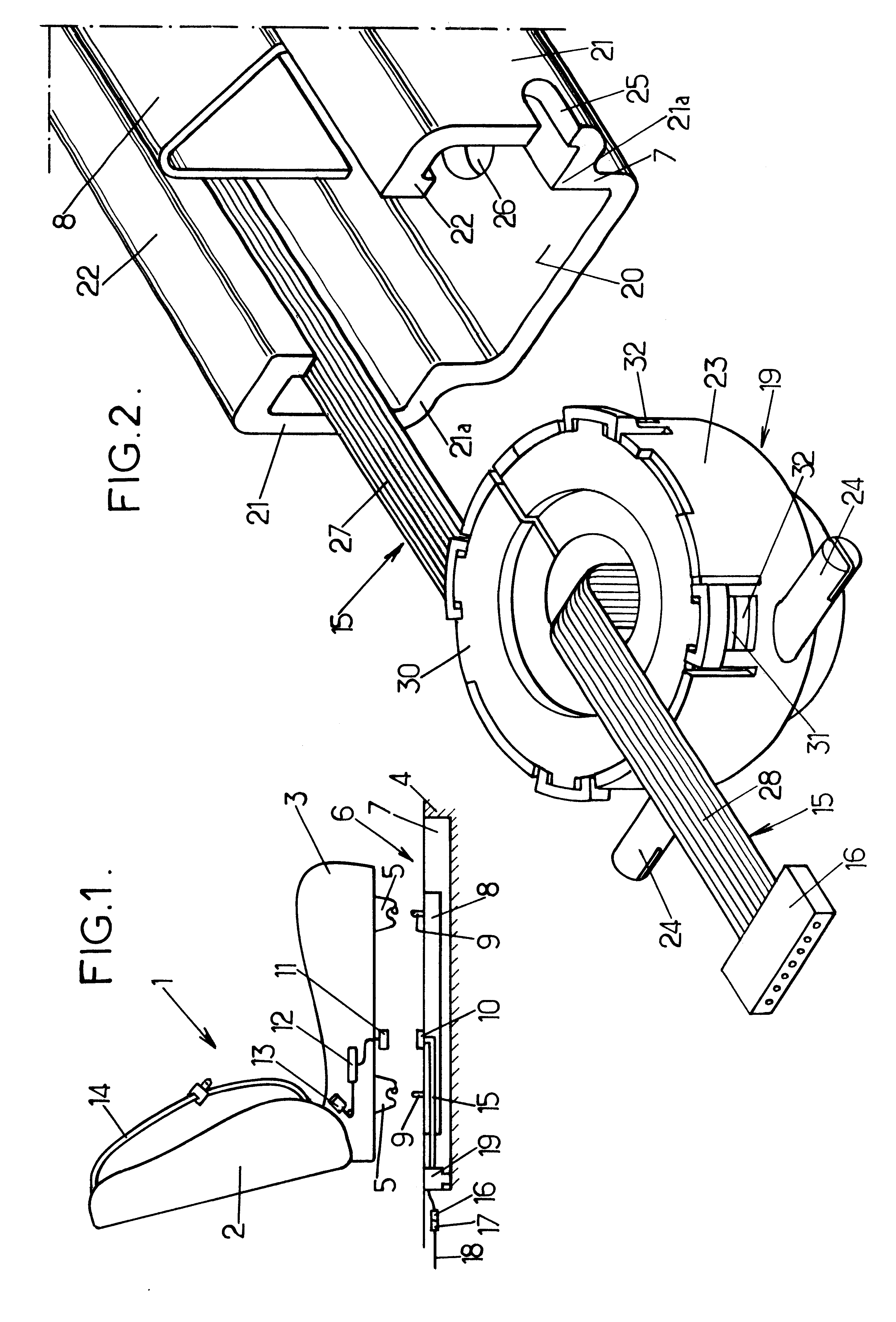
It differs simply from the first embodiment explained above by the fact that the resilient return drum 19 is no longer fixed to the fixed section go the slide rail, but to the shuttle 8. The section 27 of the flexible cable 15 extends then from said drum to the connector 16 which is connected to the fixed electrical circuit situated in the vehicle floor.

In this case, the section 28 of the flexible cabling can possibly be removed or reduced to the strict minimum, since the connector 10 carried by the shuttle 8 can then be fixed directly on the drum 19, and in particular on the cover 30 of the fixed drum.


PUM


Abstract

A slide rail for a removable vehicle seat comprises a fixed section and a shuttle sliding on this section. The shuttle carries a connector connected to the seat, and this connector is connected to an electrical circuit belonging to the vehicle floor by means of a flexible electrical cabling which is arranged under a flange of the fixed section and which is held taut by a resilient return drum.

Description

The present invention relates to slide rails for removable seats of vehicles.More particularly, the invention relates to a slide rail for a removable vehicle seat comprising:a fixed section intended to be fixed with the vehicle floor and along which the seat can slide, this fixed section comprising first and second longitudinal ends and having at least one flange under which a free space is delimited, said flange extending from the first end to near the second end of the fixed section,and at least one shuttle sliding mounted relative to the fixed section and adapted to be connected to the vehicle seat so as to follow the movement of the seat along said fixed section.By removable seat, it is understood here a seat which can be entirely removed from the vehicle, or which can at least be moved so as to free a large part of the vehicle floor zone normally situated under the seat (it can relate to for example a tipping seat in the approximately vertical position or "pocket book" position...

Claims


Application Information

Patent Timeline
Patent Type & Authority Patents(United States)
IPC IPC(8): B60N2/02B60N2/07B60N2/06
CPCB60N2/0224H02G11/02B60N2/0715B60N2002/0264B60N2/0732B60N2/0264
Inventor CRESSEAUX, GILLES
Owner BERTRAND FAURE EQUIP SA (FR)
Why Eureka
Try Eureka