Valve seat self cleaning device for alumina production plants

Inactive Publication Date: 2001-08-14
AMPO
View PDF8 Cites 4 Cited by
  • Summary
  • Abstract
  • Description
  • Claims
  • Application Information

AI Technical Summary

Benefits of technology

The valve for alumina obtaining installations disclosed has been conceived to solve the above described problem, by incorporating a device which allows internal self-cleaning

Problems solved by technology

At installations where this type of process is carried out, over time bauxite adheres to valve seats, and although occasionally this problem may result in the bauxite acting as a sealant between the valve disc or ring and the seat, the general results in that the disc cannot rest properly on the valve seat.

Method used


Image

  • Valve seat self cleaning device for alumina production plants
  • Valve seat self cleaning device for alumina production plants
  • Valve seat self cleaning device for alumina production plants

Examples


Embodiment Construction

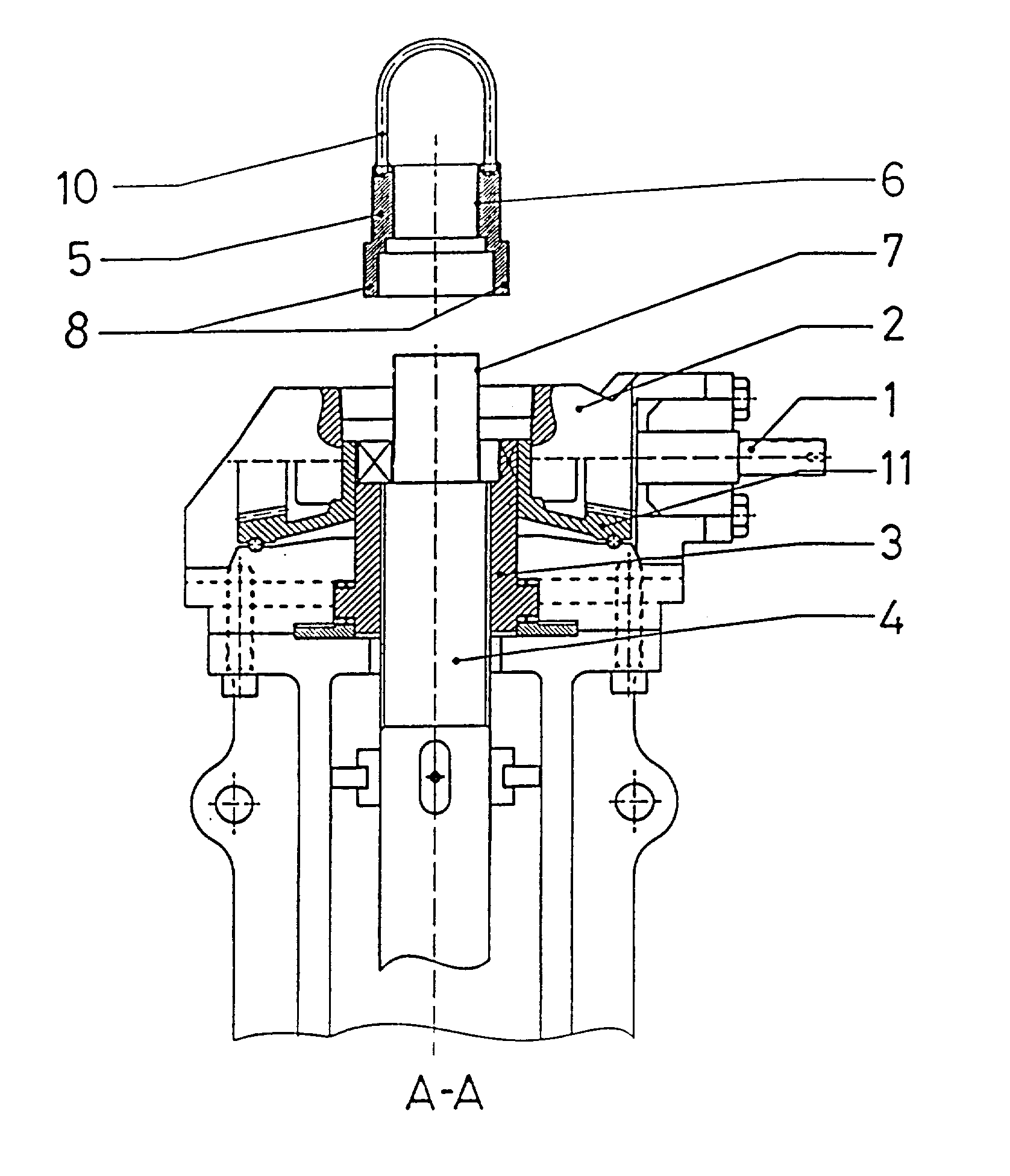
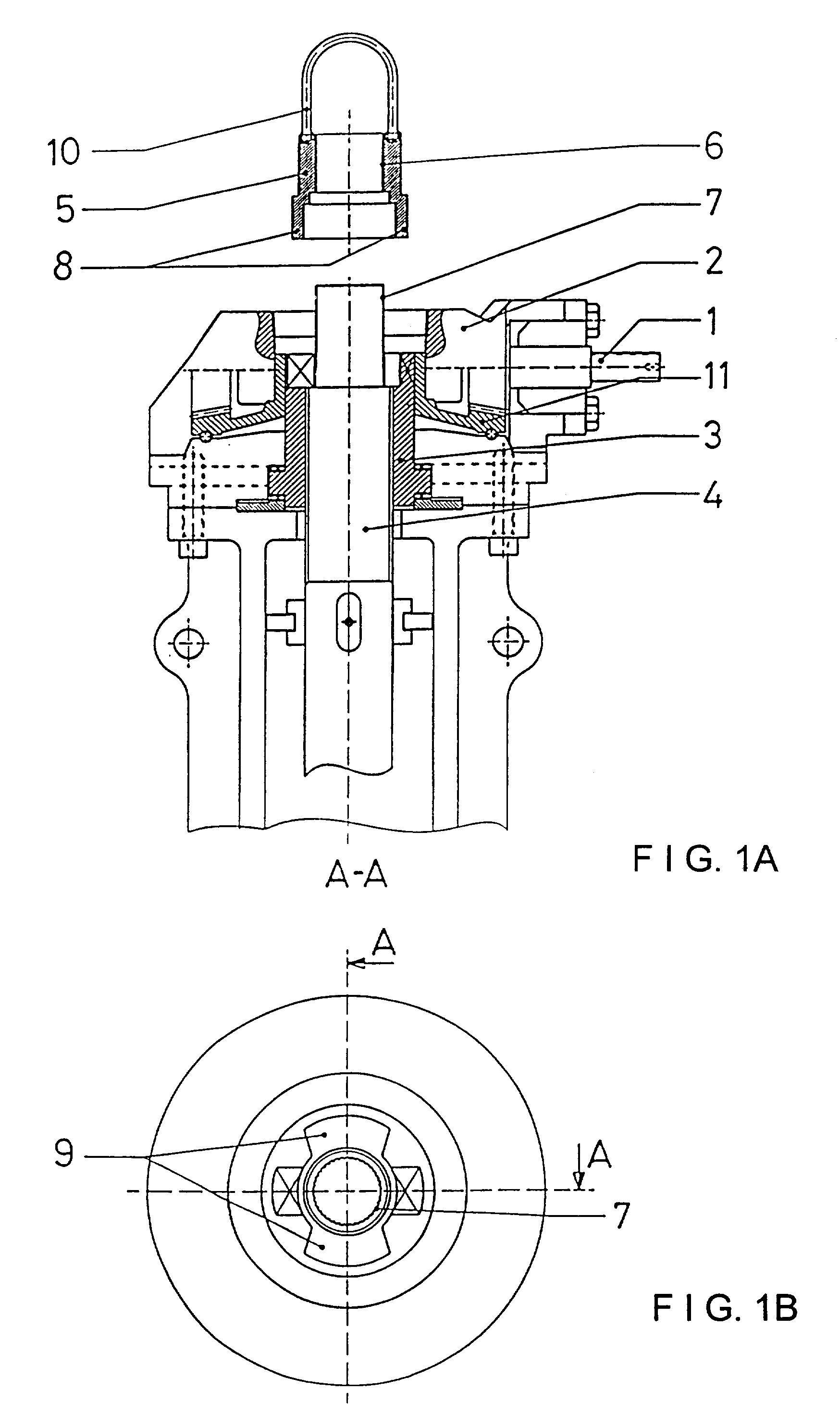
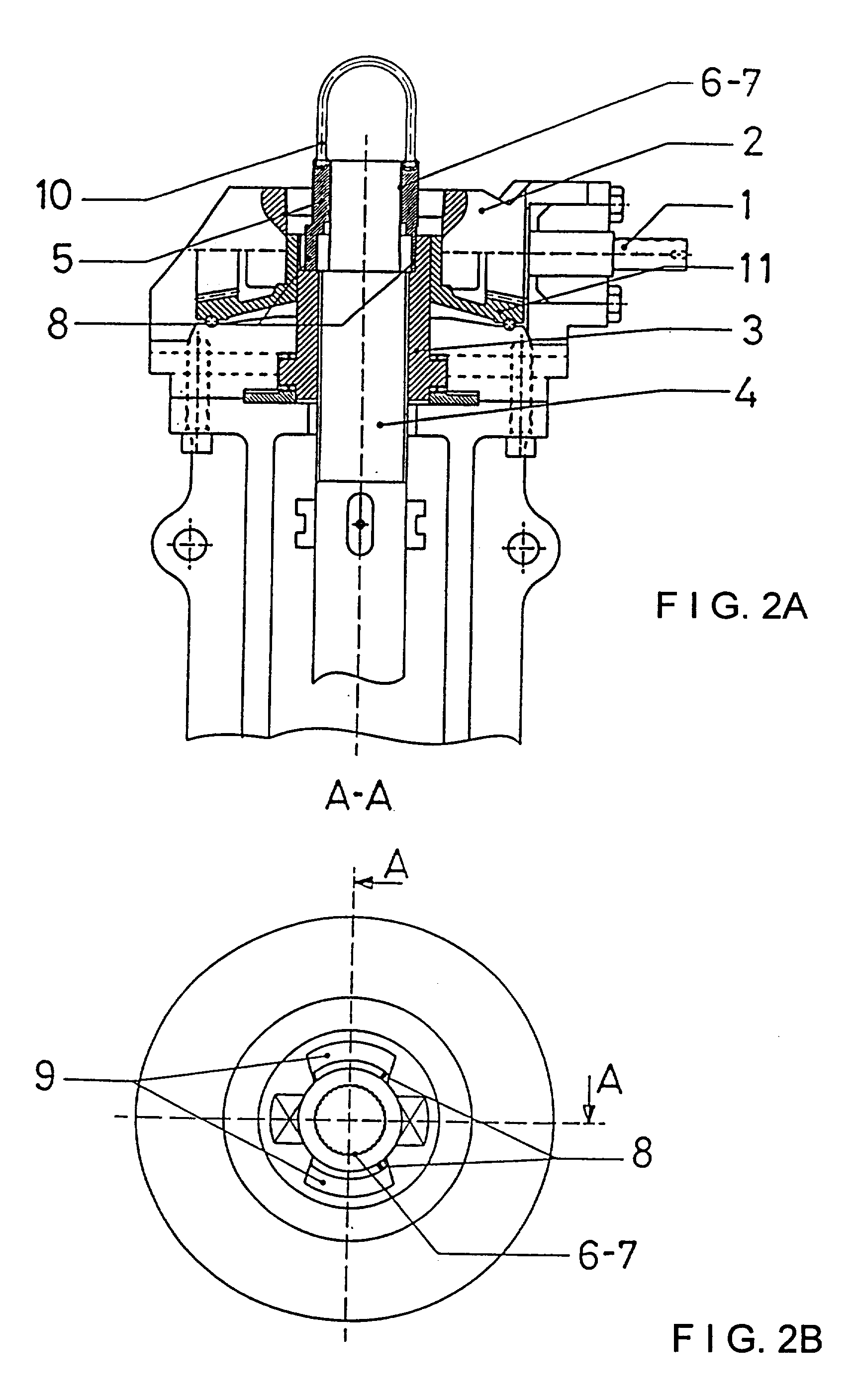
FIGS. 1 and 2 show the valve unit partially, showing only the valve shaft (4) inside the top part of the valve body. The shaft (4) acts as a spindle as it is inside spindle nut (3), which rotates due to the action of drive shaft (1) which transmits its motion to nut (3) through bevel gear (2) and crown (11), making said valve shaft (4) ascend or descend. For this, the spindle nut is provided with upper projections in the shape of battlements (12) which couple to corresponding recesses made in crown (11) so that, in its rotation, the crown carries spindle nut (3).

The top end of valve shaft (4) is accessible from the top and is provided in its side wall with a toothing (7) which is visible in FIG. 1B.

The device employed to perform self-cleaning of the valve consists of a locking cap (5) which allows to engage crown (11) and valve shaft (4) so that shaft, crown and spindle nut rotate simultaneously. The locking cap, shown in FIG. 3, comprises a cylindrical body with different internal ...


PUM


Abstract

This valve is applicable in conduction of bauxite in pipes and is meant to allow the self-cleaning of the valve with the aid of a locking cap which connects the drive crown and the valve shaft, causing the rotation of said crown to be transmitted to the valve shaft, which as it rotates rubs on the valve seats, thus removing the depositions.

Description

OBJECT OF THE INVENTIONThe present invention relates to a device applicable to valves in alumina obtaining installations with the object of providing self-cleaning of bauxite depositions inside the valve body, by rotation and scraping of seats inside the valve body.As is known, aluminum is obtained by electrolysis from bauxite, with the bauxite passing through several phases or process stages before alumina, and afterwards aluminum may be obtained.At installations where this type of process is carried out, over time bauxite adheres to valve seats, and although occasionally this problem may result in the bauxite acting as a sealant between the valve disc or ring and the seat, the general results in that the disc cannot rest properly on the valve seat.These depositions inside the valve must be removed manually.This type of valves comprises a rod or shaft with a disc or seal solidly joined to it which is housed inside the valve body, so that these elements make up the valve itself.The ...

Claims


Application Information

Patent Timeline
IPC IPC(8): F16K31/50F16K31/44F16K29/00F16K31/53
CPCF16K31/50F16K29/00Y10T137/4322Y10T137/6253F16K31/53
Inventor GONI USABIAGA, JUAN JOSE
Owner AMPO
Why Eureka
Try Eureka