
Friction-band brake

a friction-band and brake technology, applied in the direction of friction lining, gearing details, mechanical equipment, etc., can solve the problem of not being equally suited to braking rotational movement in different directions

Inactive Publication Date: 2002-02-26
ROBERT BOSCH GMBH
View PDF5 Cites 6 Cited by
  • Summary
  • Abstract
  • Description
  • Claims
  • Application Information

AI Technical Summary

Problems solved by technology

A disadvantage of this known friction belt brake is that it is not equally suited to braking rotational movements in different directions.

Method used


Image

  • Friction-band brake
  • Friction-band brake
  • Friction-band brake

Examples


Embodiment Construction

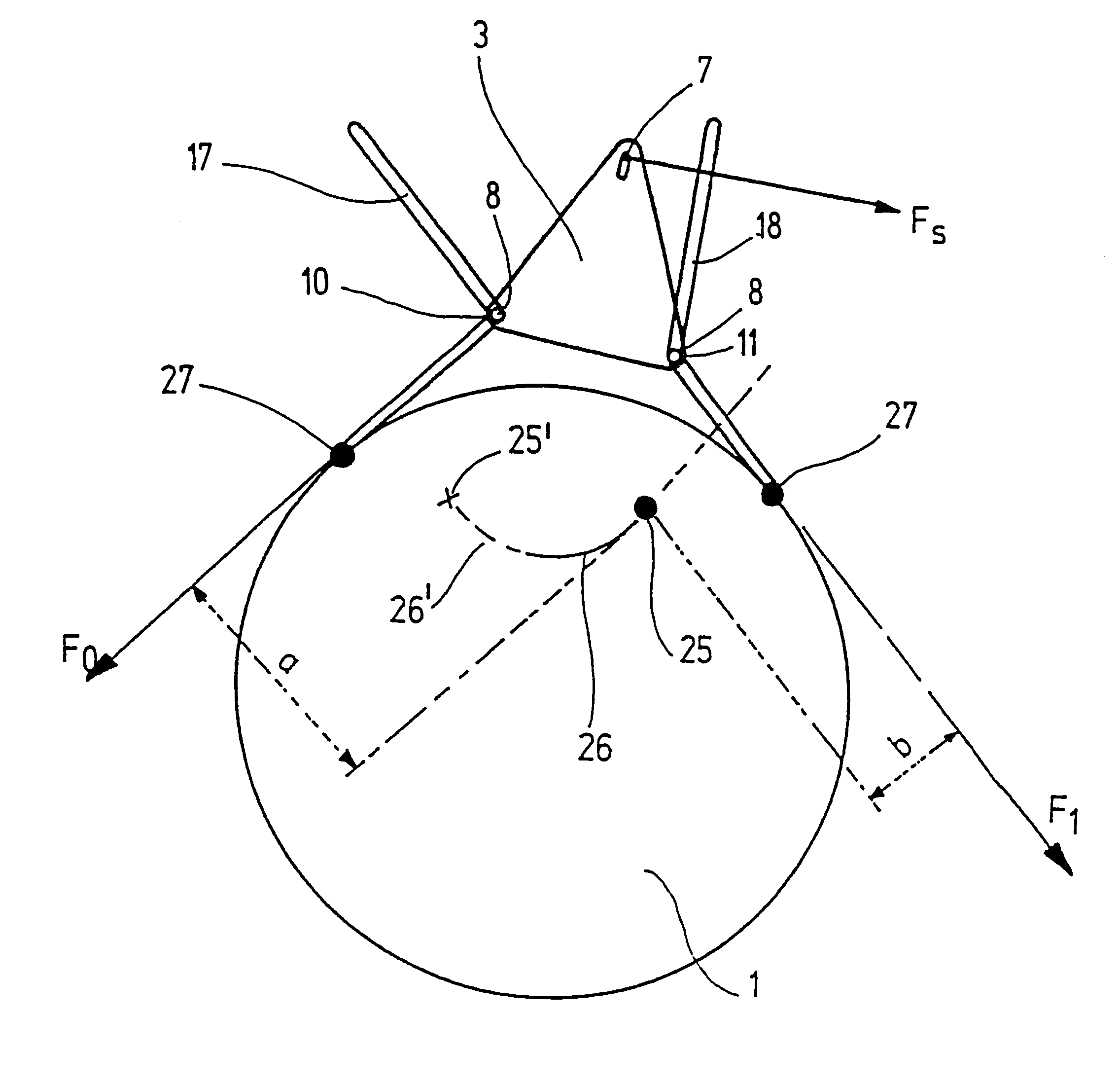
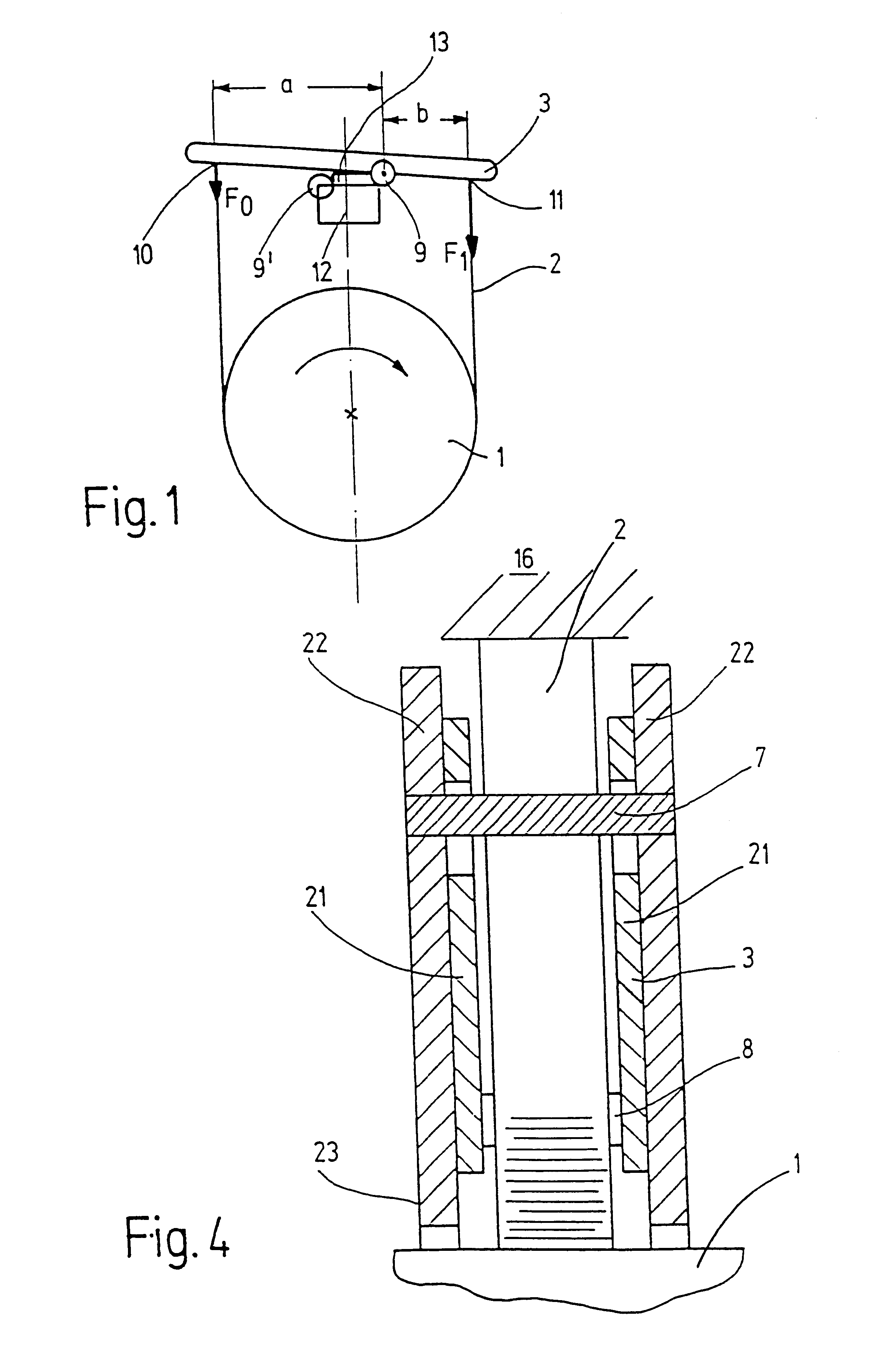
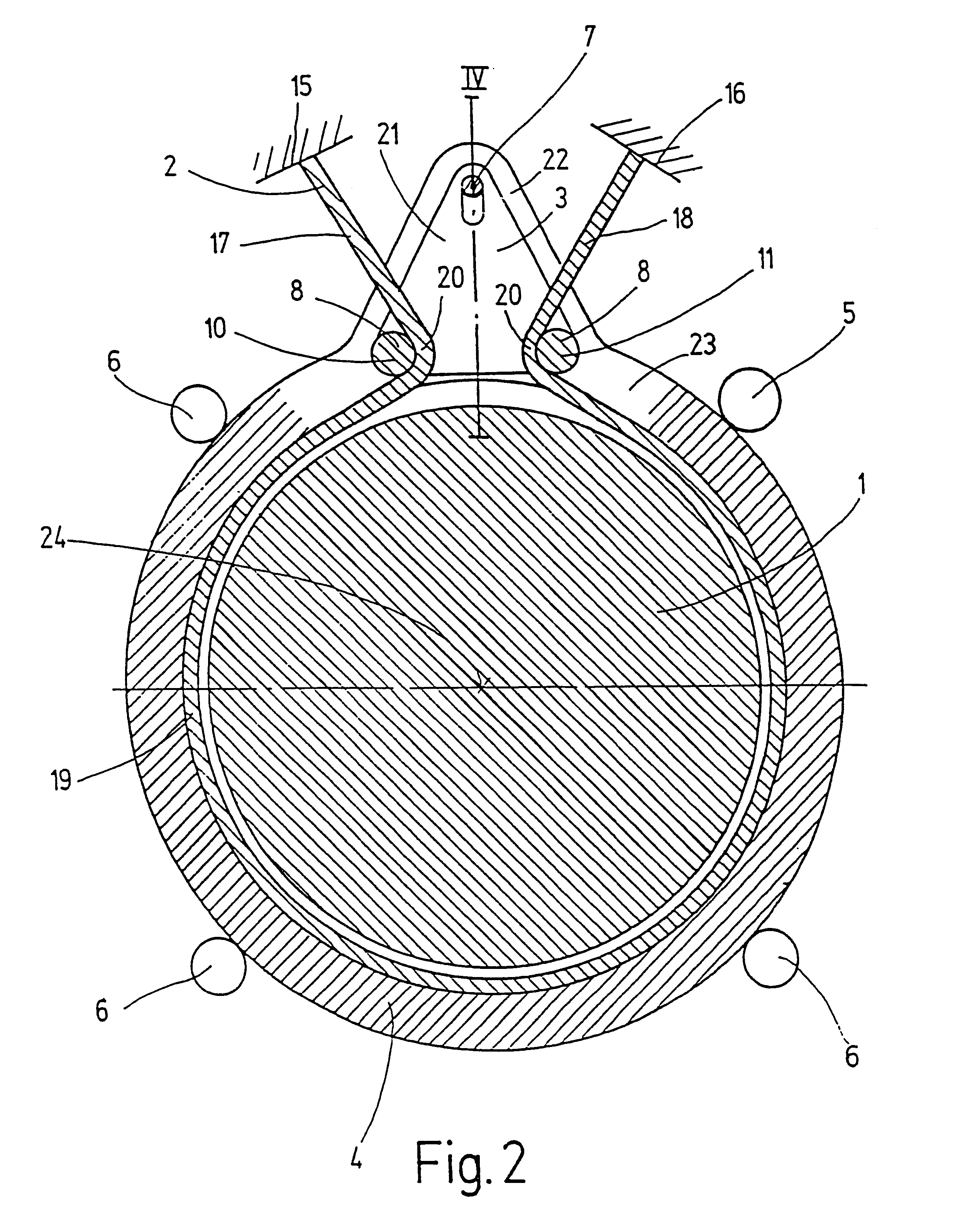
In a very schematic fashion, FIG. 1 shows a friction belt brake according to a first exemplary embodiment of the invention. On a base 12 that is fixed in relation to the rotary cylinder 1, a support 3 is supported so that it can pivot around two joints 9, 9'. A first of these joints 9' connects the base 12 to a plate 13 that rests flat against the base 12 in the braking position shown. A second joint 9 at the opposite end of the plate 13 connects this plate to a support 3 which is engaged at the securing points 10, 11 by a friction belt 2. In the depicted position of the support 3, the securing point 10 is lifted up and the friction belt 2 is stretched tight around the rotary cylinder 1. As in the conventional friction belt brake shown in FIG. 6, the clockwise rotating rotary cylinder 1 exerts a force F.sub.1 on the securing point 11 that is greater than the force F.sub.0 on the securing point 10. This produces an effective braking of a clockwise rotation.

In order to brake a counter...


PUM


Abstract

In a friction belt brake with a rotary cylinder (1), which is wound around at least a part of its circumference by a friction belt (2), and with a support (3) for the friction belt, which in a first braking position, can be pivoted around a first axis (9; 25) and two securing points (10, 11) for respectively opposite end sections of the friction belt, wherein a first of the two securing points has a longer lever arm (a) in relation to the first axis than the second securing point (11), the provision is made that in a second braking position, the support (3) can be pivoted around a second axis with regard to which the second securing point has a longer lever arm than the first.

Description

PRIOR ARTThe invention relates to a friction belt brake with a rotary cylinder which is wound around at least part of its circumference by a friction belt, and with a support for the friction belt which, in a first braking position, can be pivoted around a first axis and has two securing points for respectively opposite end sections of the friction belt. In this connection, a first of the two securing points has a longer lever arm in relation to this first axis than the second securing point.A differentially acting friction belt brake of this kind is shown in FIG. 6. The figure depicts a rotary cylinder 1 rotating in the clockwise direction, with a friction belt 2 that is fastened to a support 3 at two securing points 10, 11. The support 3 can rotate around a fixed axis 9 disposed between the securing points; the securing points consequently define lever arms with the lengths a and b in relation to this axis 9.The distance a+b between the securing points 10, 11 here is equal to the ...

Claims


Application Information

Patent Timeline
Patent Type & Authority Patents(United States)
IPC IPC(8): F16D49/00F16D49/10F16H63/30
CPCF16D49/10F16H63/3003
Inventor TUMBACK, STEFANBOLZ, MARTIN-PETER
Owner ROBERT BOSCH GMBH
Learn More