Window drain

a technology for draining systems and windows, applied in roof coverings, roof tools, building components, etc., can solve problems such as damage to ceilings and plastered walls, rainwater infiltrating under the sill, and rainwater leakage through walls,

Inactive Publication Date: 2002-05-14
WARK SCOTT ARTHUR
View PDF4 Cites 113 Cited by
  • Summary
  • Abstract
  • Description
  • Claims
  • Application Information

AI Technical Summary

Benefits of technology

It is yet another objective of the present invention to provide versatile window drains, adaptable to be assembled with standard windows having different widths and lengths.

Problems solved by technology

In the wall construction for buildings, usually the sill of the window frame merely rests upon the boarding and, until now, no efficient devices to prevent the penetration of water or moisture under the window sill have been developed and successfully used.
As a direct result, rain water infiltrates into under the sill and leaks down through the wall of the building and damages ceilings and plastered walls.
If the house happens to be covered with a stucco finish, the water also enters between the furring and the stucco, so that the stucco becomes discolored and sometimes falls away beneath the window.
Despite various improvements in the existing window drains, the latter still suffer from drawbacks which are seemingly inherent in their basic concepts.
Second, since no rear upstanding rib or flange is used, the leakage of water towards the back of the window frame cannot be prevented.
Third, the manner of attachment of the drip deflector to the sill of the window frame by a series of nails, introduced from under the drip deflector, requires a completion of this operation prior the window frame is installed in a building wall.
First, the use of valves renders the device very complicated.
Second, the reliability of the system is quite questionable, especially in severe meteorological conditions.
There are two basic disadvantages to this moisture guard design.
First, the sill of the window rests directly on the metal facing and, thus, no space for water collection is provided.
Second, the metal facing is not provided with a sloping surface for drainage.

Method used


Image

  • Window drain
  • Window drain
  • Window drain

Examples


first embodiment

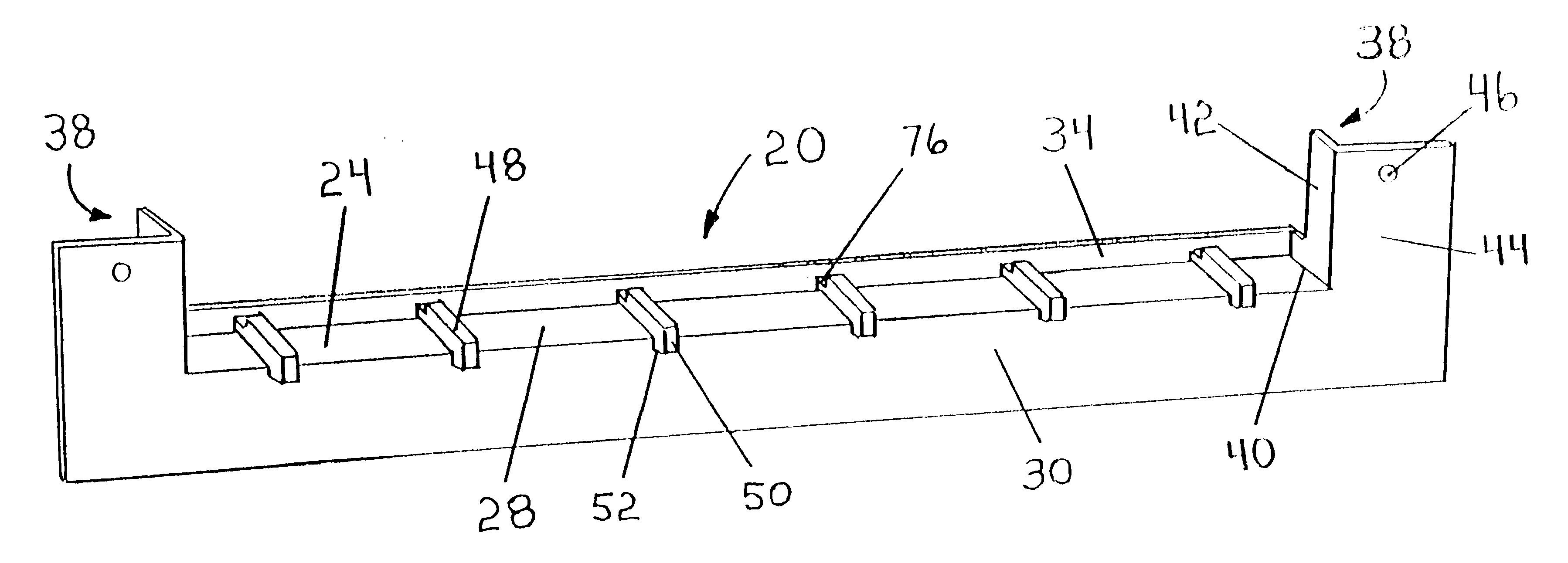
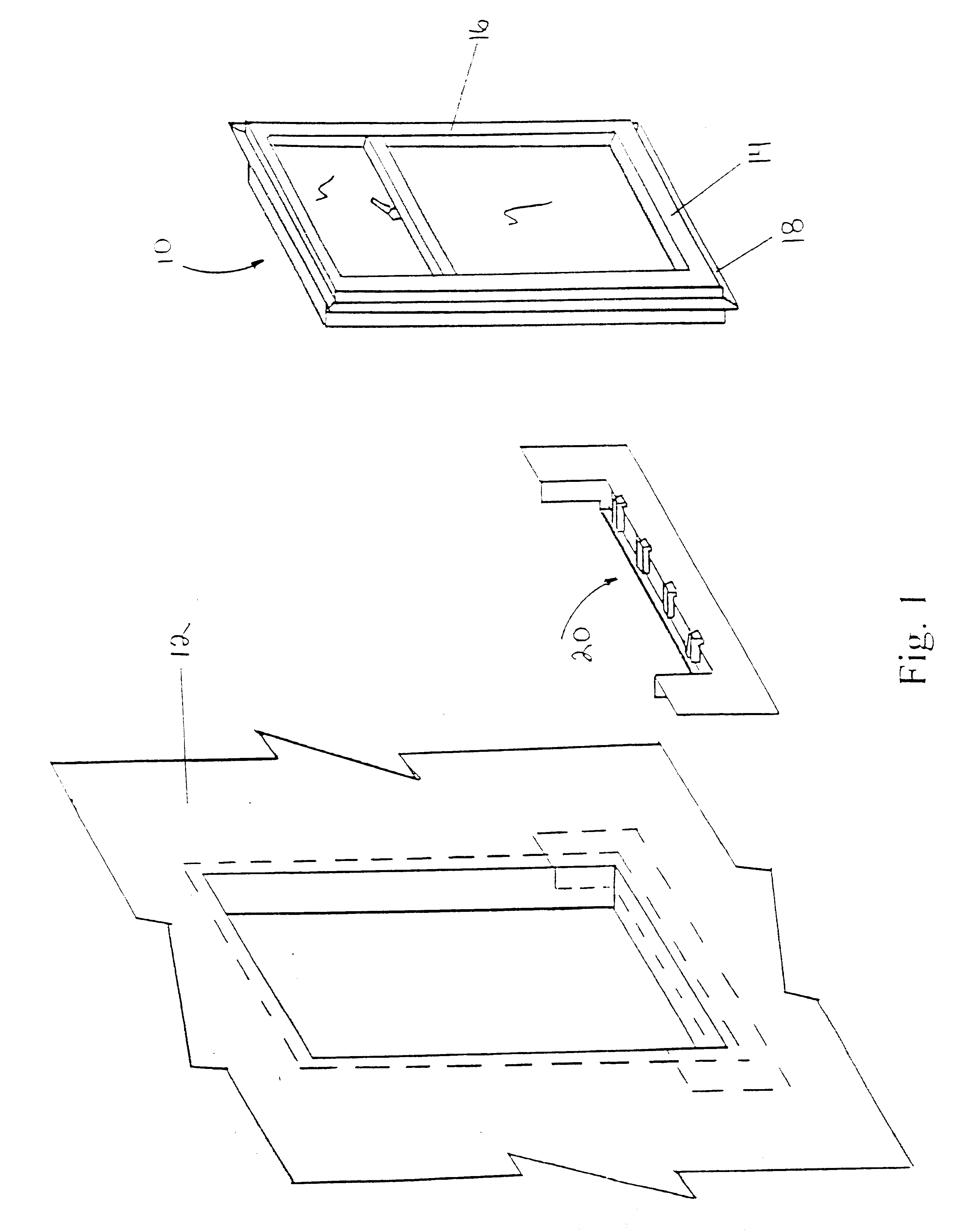
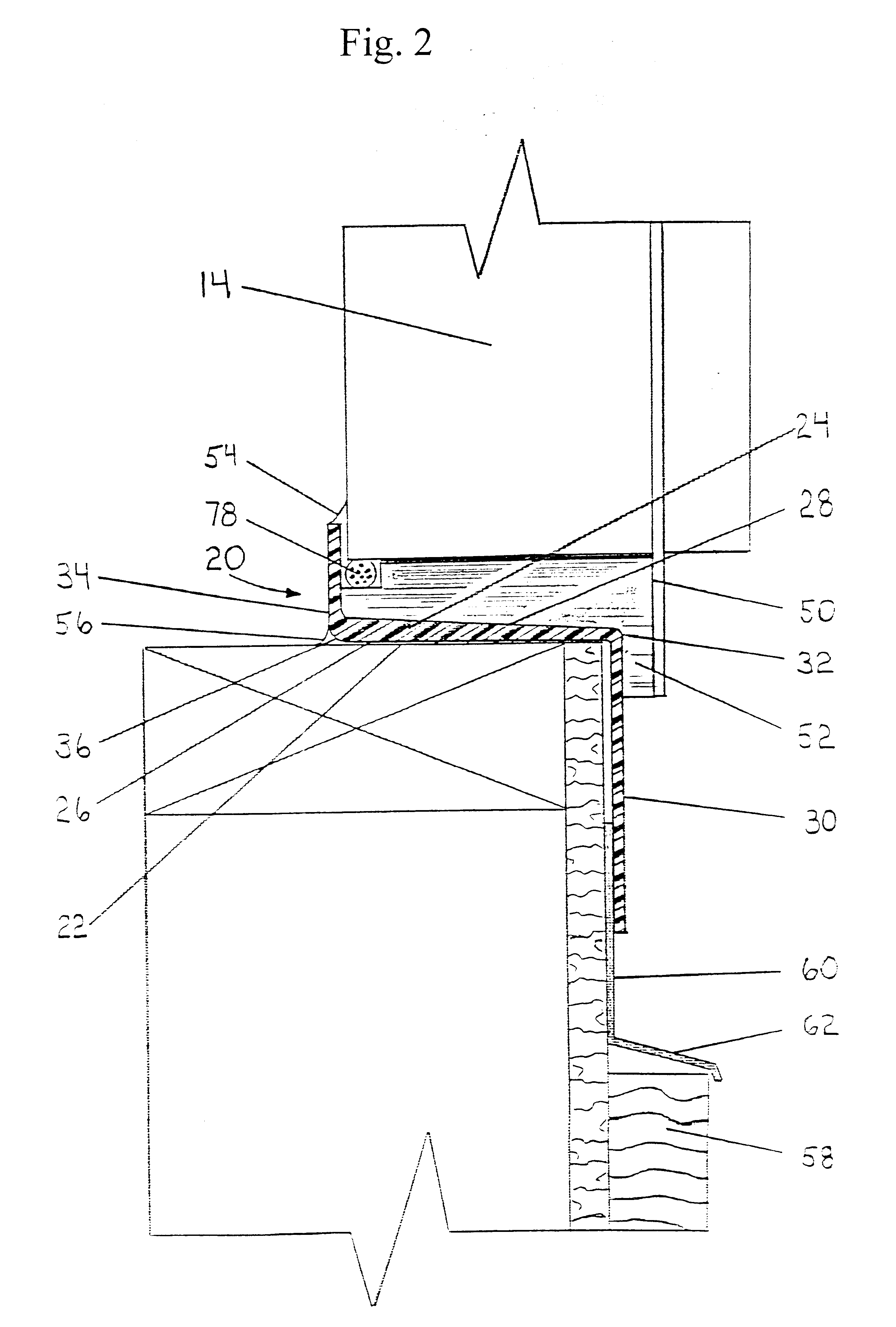
With reference to the FIGS. 2, 3 and 3A, there is shown in a first embodiment, a window drain, generally indicated at 20. The latter is positioned beneath sill 14 and is seated on a paper flashing 22.

Window drain 20, which is advantageously formed by molding, comprises a base 24 having a horizontally extending lower surface 26 and a sloping downwardly and outwardly upper surface 28. Base 24 has a substantially rectangular shape in plan. Horizontally extending lower surface 26 of base 24 lies directly on paper flashing 22.

A front flange 30 projects perpendicularly and downwardly from the front edge 32 of base 24. Front flange 30 is integrally formed with base 24 and abuts against paper flashing 22. The latter extends from under base 24 and is disposed on building wall 12.

An upstanding rear rib 34 is situated at the rear edge 36 of base 24, from which it extends perpendicularly and upwardly and with which it is integrally formed.

An end flange 38 is located at each lateral edge 40 of b...

second embodiment

In a second embodiment, shown diagrammatically in FIGS. 4 and 4A, window drain 64 is designed to accommodate windows 10 of different standard widths. To this end, the above described embodiment is modified as follows: a base 66, wider than base 24, is used. Base 66 incorporates a supplementary rear rib 68. The latter is situated behind and parallel to upstanding rear rib 34 and projects outwardly from the back edge of base 24. In this embodiment the top of upstanding rear rib 34 is coplanar with the tops of window supports 48, while the top of supplementary rear rib 68 is relatively higher. The distance between supplementary rear rib 68 and front ends 50 or spacers 52 is adaptable to accommodate a window 10 having the widest standard width, respectively the largest distance between the back edge of sill 14 and the back face of window flange 18.

Distances between intermediary lines situated between rear rib 68 and upstanding rear rib 34, on one side, and front ends 50 or the front fac...

third embodiment

In a third embodiment shown in FIG. 5, a window drain 74 is adaptable to accommodate, in situ, windows 10 of different standard widths. To this end, the above described embodiment is modified as follows: upstanding rear rib 34 and supplementary rear rib 68 are provided with coplanar tops, which are relatively higher than the tops of window supports 48. When a window drain 74 is used for a window 10 having the narrowest standard width, supplementary rear rib 68 together with the part of base 24, between upstanding rear rib 34 and supplementary rear rib 68, are cut and discarded. In this case, the back of sill 14 abuts upstanding rear rib 34. A corresponding upper caulking seam 54 is used.

When a window 10 having an intermediary or the largest standard width is used, the height of upstanding rear rib 34 is reduced by cutting the latter to the level of the tops of window supports 48. Thus, a corresponding part of upstanding rear rib 34 is cut and discarded. Obviously, in this case use i...


PUM


Abstract

Window drain comprises, in general, a base having a horizontally extending lower surface and a sloping downwardly and outwardly upper surface. To the base are connected: a front flange, an upstanding rear rib, an end flange at each end, window supports and spacers attached on the front flange. In one embodiment, the window drain is made for a window of a specific width. In another embodiment, the window drain, is versatile so it can be used for windows of different widths. In a third embodiment, the window drain can be made, in situ, for different window widths.

Description

1. Field of the InventionThis invention relates, in general, to drainage systems for buildings and, particularly, to a window drain.2. Description of the Prior ArtIn the wall construction for buildings, usually the sill of the window frame merely rests upon the boarding and, until now, no efficient devices to prevent the penetration of water or moisture under the window sill have been developed and successfully used. As a direct result, rain water infiltrates into under the sill and leaks down through the wall of the building and damages ceilings and plastered walls. If the house happens to be covered with a stucco finish, the water also enters between the furring and the stucco, so that the stucco becomes discolored and sometimes falls away beneath the window.Despite various improvements in the existing window drains, the latter still suffer from drawbacks which are seemingly inherent in their basic concepts. For example, U.S. Pat. No. 2,648,107, granted on Aug. 11, 1953 to Bates f...

Claims


Application Information

Patent Timeline
Patent Type & Authority Patents(United States)
IPC IPC(8): E06B7/14
CPCE06B7/14
Inventor WARK, SCOTT ARTHUR
Owner WARK SCOTT ARTHUR
Why Eureka
Try Eureka