Miter cutting guide apparatus

a technology of guide apparatus and miter, which is applied in the field of miters, can solve the problems of less than satisfactory process, more difficult cuts, and a large amount of time spent measuring, calculating and setting

Inactive Publication Date: 2002-06-11
ROWE JAMES T
View PDF7 Cites 25 Cited by
  • Summary
  • Abstract
  • Description
  • Claims
  • Application Information

AI Technical Summary

Problems solved by technology

One of the more difficult cuts to make is a miter cut for inside or outside corners.
However, in many situations such as angled walls, counter tops and th...

Method used


Image

  • Miter cutting guide apparatus
  • Miter cutting guide apparatus
  • Miter cutting guide apparatus

Examples


Embodiment Construction

of the Figures

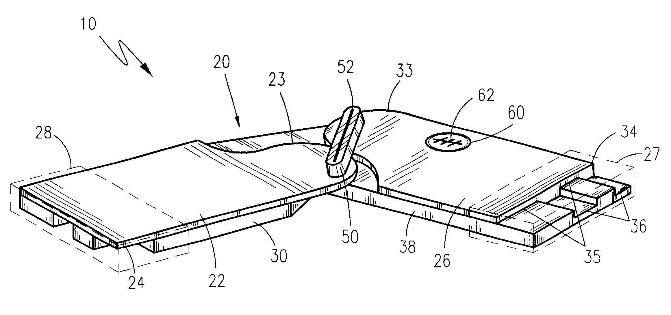
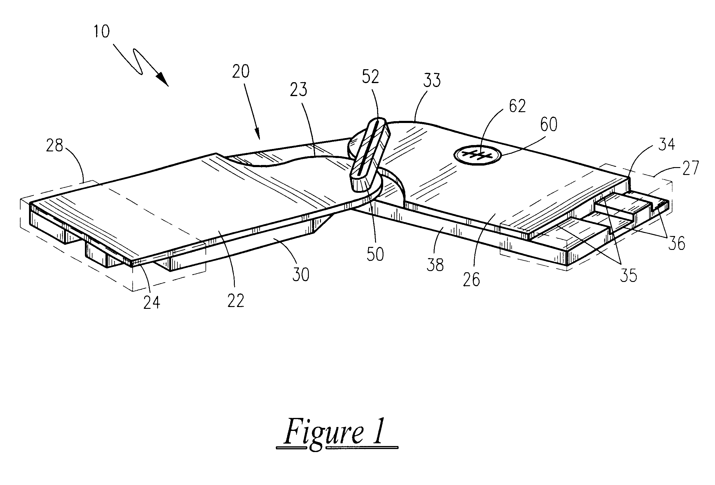
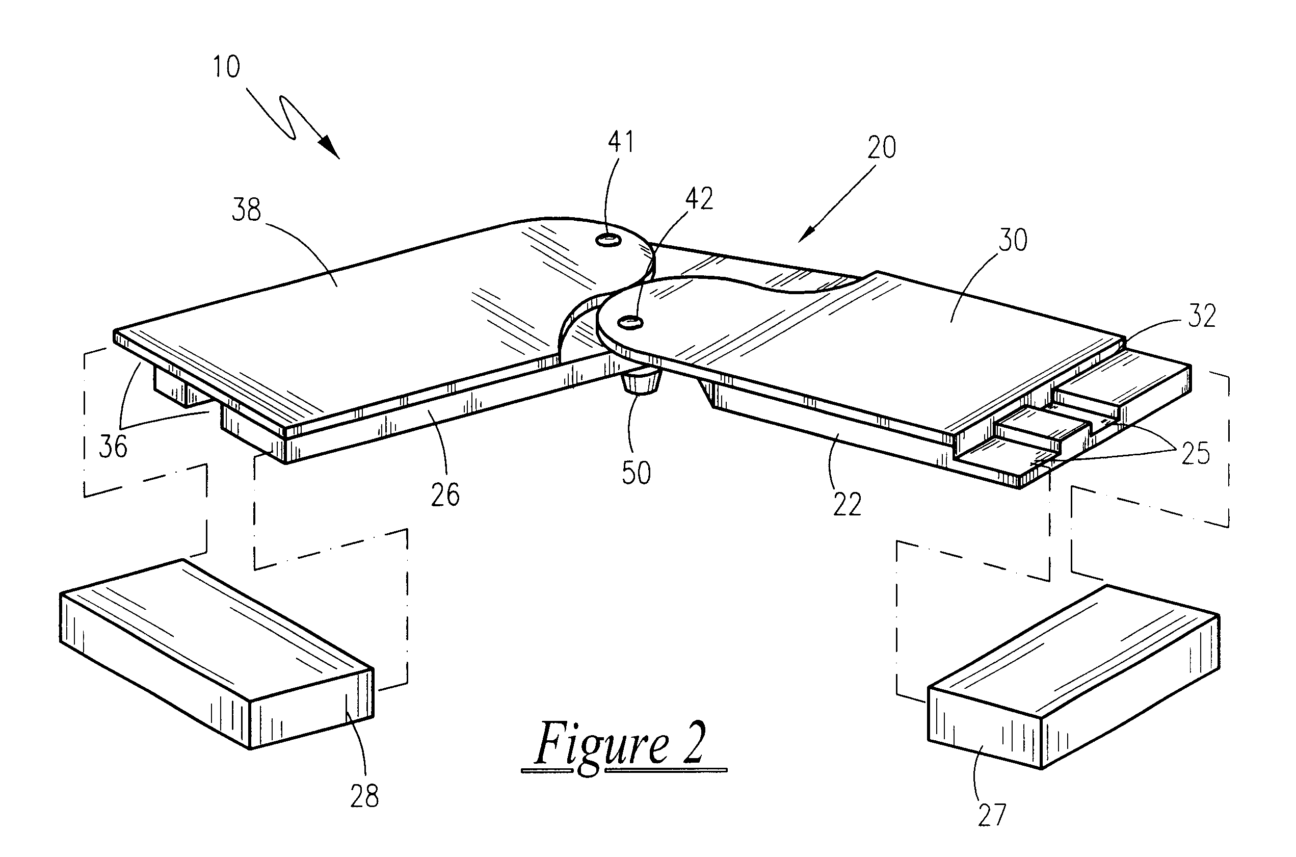
Referring now to FIGS. 1-3, a miter cutting guide apparatus 10 is shown, according to the present invention, comprised of a miter arm pivot assembly 20 which includes a first miter arm 22 pivotally attached to a second miter arm 26, a slidable centerbar 50 and an angle measuring gauge 62 for meeting a consummate standard for making miter cuts used on wood millwork as trim around floors, walls, cabinets and the like.

The apparatus 10 is formed of plastic or other material capable of injection molding, and therefore can be formed easily of recycled material.

The first miter arm 22 is of a generally, linearly elongated rectangular configuration, having an anterior end 23 opposite a posterior end 24. The anterior end 23 of the first miter arm 22 forming a tapered portion. The first miter arm 22 further having channeled grooves 25 extending the entire linear length along an underside thereof for slidably engaging complementary grooves 32 formed in a first complementary base 3...


PUM

PropertyMeasurementUnit
Lengthaaaaaaaaaa
Distanceaaaaaaaaaa

Abstract

A miter cutting guide apparatus is provided to aid in the making of miter cuts used on wood millwork as trim around floors, walls, doors, cabinets and the like and which can also be used on ceramics such as for tile cutting. Two miter arms are pivotally attached by a pivot locking means such as a screw. Each miter arm has a complementary base resting underneath and being guidably received by each miter arm, thereby allowing each miter arm to reciprocate along its complementary base.

Description

1. Field of the InventionThe present invention relates generally to miters used for cutting materials on table saws, router tables, band saws and other types of shaping and cutting tools and, more particularly, to a miter guide cutting apparatus.2. Description of the Related ArtConstruction and wood working projects require a variety of tools and accessories in order to ensure proper measurements for sizing pieces prior to performing cuts and / or assembly. One of the more difficult cuts to make is a miter cut for inside or outside corners. These cuts are commonly used on wood millwork or molding as trim around floors, walls, doors, cabinets and the like, and as such are usually visible to any observer at the completion of a project. A common 45 degree angle cut will work as long as the surfaces are perfectly square. However, in many situations such as angled walls, counter tops and the like they are not. Even walls that should be perfectly square commonly are not. During these occasi...

Claims


Application Information

Patent Timeline
IPC IPC(8): G01B3/56
CPCG01B3/56Y10T83/8889Y10T83/8773Y10T83/8878
Inventor ROWE, JAMES T.
Owner ROWE JAMES T
Why Eureka
Try Eureka