
Humerus head prosthesis

a head and humerus technology, applied in the field of humerus head prosthesis, can solve the problems of inability to provide practicable and reliable help for previously known humerus head prosthesis, and the inability to integrate the tubercles at the prosthesis

Inactive Publication Date: 2002-06-18
ZIMMER GMBH
View PDF7 Cites 61 Cited by
  • Summary
  • Abstract
  • Description
  • Claims
  • Application Information

AI Technical Summary

Problems solved by technology

In humerus head prostheses there is the problem of the bone integration of the tubercles at the prosthesis.
The previously known humerus head prosthesis offers no practicable and reliable help for this.

Method used


Image

  • Humerus head prosthesis
  • Humerus head prosthesis

Examples


Embodiment Construction

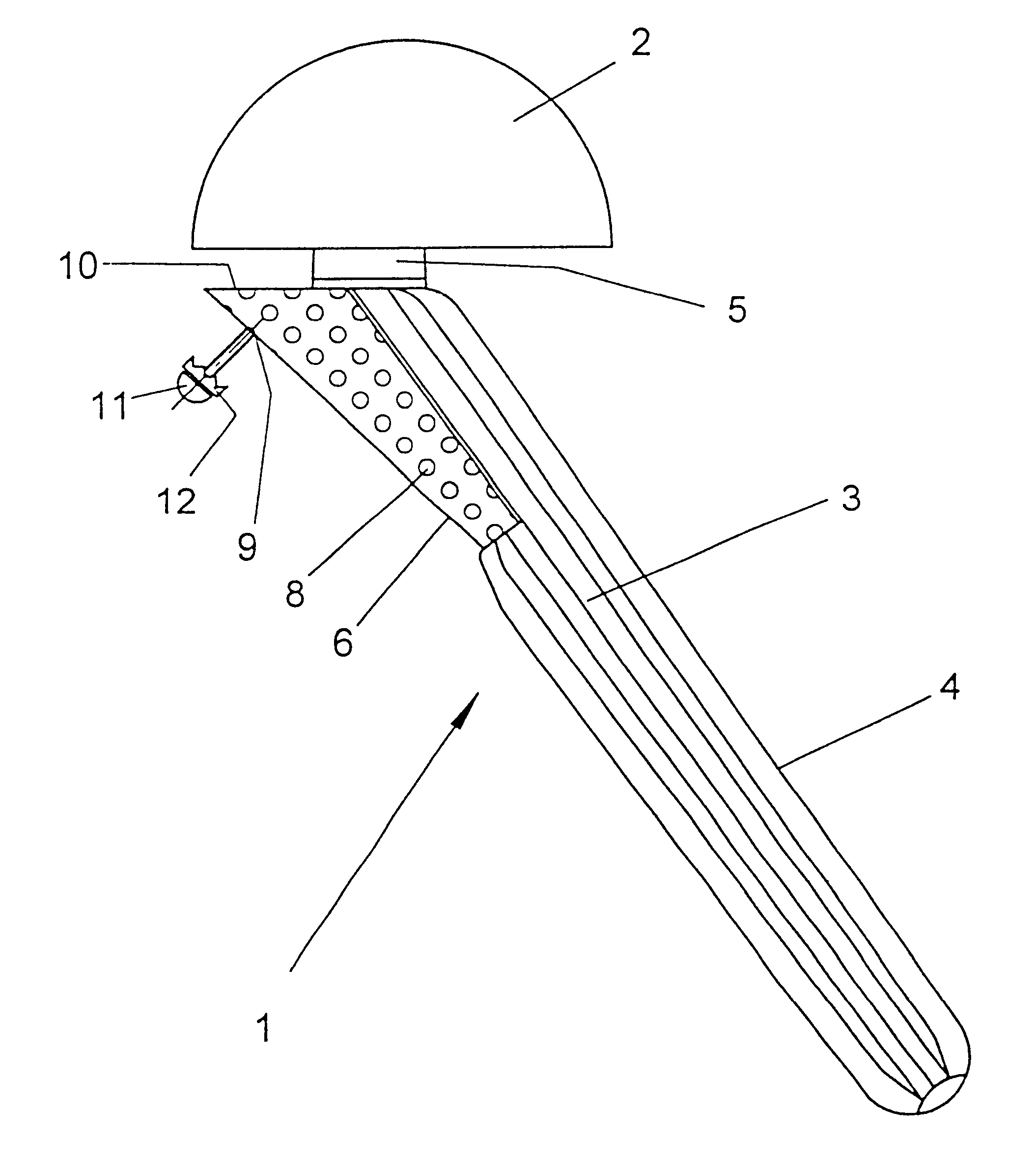
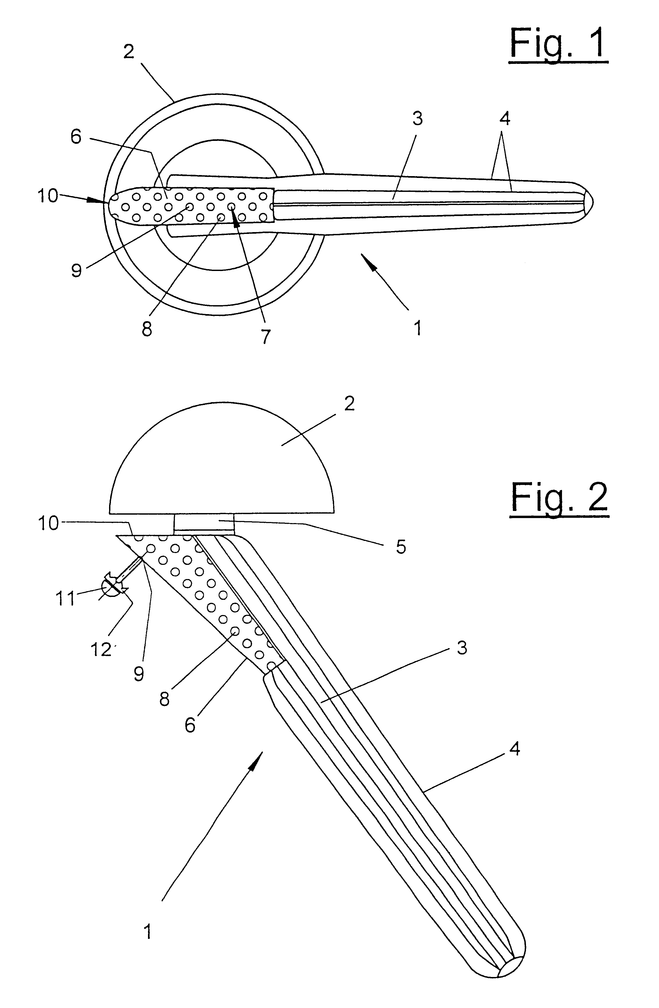
The humerus head prosthesis (1) consists of a substantially hemispherical head (2) and a shaft (3), which are connected via a neck (5). The connection between the neck (5) and the head (2) can be releasable. The humerus head prosthesis (1) can have any desired suitable shape in the shaft and head region.

A hollow quiver (6) is arranged laterally at the prosthesis shaft (3) for the reception of bone shavings, bone splinters or the like. The quiver (6) is located subcapitally at the level of the anatomical location of the tubercles and preferably terminates at the proximal end flush with the prosthesis shaft (3). In the quiver region the prosthesis shaft (3) can have a flattening or a cut-out. This facilitates on the one hand the attaching of the quiver (6) and increases the quiver volume on the other hand.

The humerus head prosthesis (1) and the quiver (6) consist of a body compatible inert material, e.g. titanium. The quiver (6) has a vaulted shape and is connected with its edges to t...


PUM


Abstract

A humerus head prosthesis including a head and a shaft. A hollow quiver which has one or more openings in the jacket is arranged at the shaft proximally and below the head. The quiver is located at the level of the anatomical position of the tubercles and laterally at the shaft. The jacket openings are formed as threaded bores for screws.

Description

1. Field of the InventionThe invention relates to a humerus head prosthesis.2. Description of the Prior ArtA humerus head prosthesis or shoulder prosthesis of this kind is known from the prior art. It has a head and a shaft. The head, which corresponds substantially to a spherical segment, can be releasably connected to the shaft via a neck. It has an eccentric bore for the neck. In humerus head prostheses there is the problem of the bone integration of the tubercles at the prosthesis. The previously known humerus head prosthesis offers no practicable and reliable help for this.The object of the present invention is therefore to provide a humerus head prosthesis with an improved integration possibility of the tubercles.The present invention provides a humerus head prosthesis that includes a hollow quiver arranged at the shaft and facilitates the integration of the tubercles at the prosthesis. It can be filled with bone shavings or bone splinters, with an ossification and a connectio...

Claims


Application Information

Patent Timeline
Patent Type & Authority Patents(United States)
IPC IPC(8): A61F2/30A61F2/40A61F2/00A61F2/28
CPCA61F2/4059A61F2/40A61F2310/00023A61F2002/2835A61F2002/30405A61F2002/30451A61F2002/30593A61F2002/30774A61F2002/30777A61F2002/30785A61F2002/30787A61F2002/30878A61F2002/30879A61F2002/4018A61F2002/4029A61F2002/4037A61F2002/4062A61F2002/4066A61F2220/0025A61F2220/0058
Inventor RUTER, AXEL
Owner ZIMMER GMBH
Learn More