Slurry useful for wire-saw slicing and evaluation of slurry

a wiresaw and slurry technology, applied in the field of slurry, can solve the problems of time and cost, and the test of ingot slicing conditions needs plenty of time and cos

Inactive Publication Date: 2002-07-23
SUPER SILICON KENKYUSHOKK +1
View PDF12 Cites 33 Cited by
  • Summary
  • Abstract
  • Description
  • Claims
  • Application Information

AI Technical Summary

Problems solved by technology

However, the test for researching ingot-slic

Method used


Image

  • Slurry useful for wire-saw slicing and evaluation of slurry
  • Slurry useful for wire-saw slicing and evaluation of slurry
  • Slurry useful for wire-saw slicing and evaluation of slurry

Examples


example

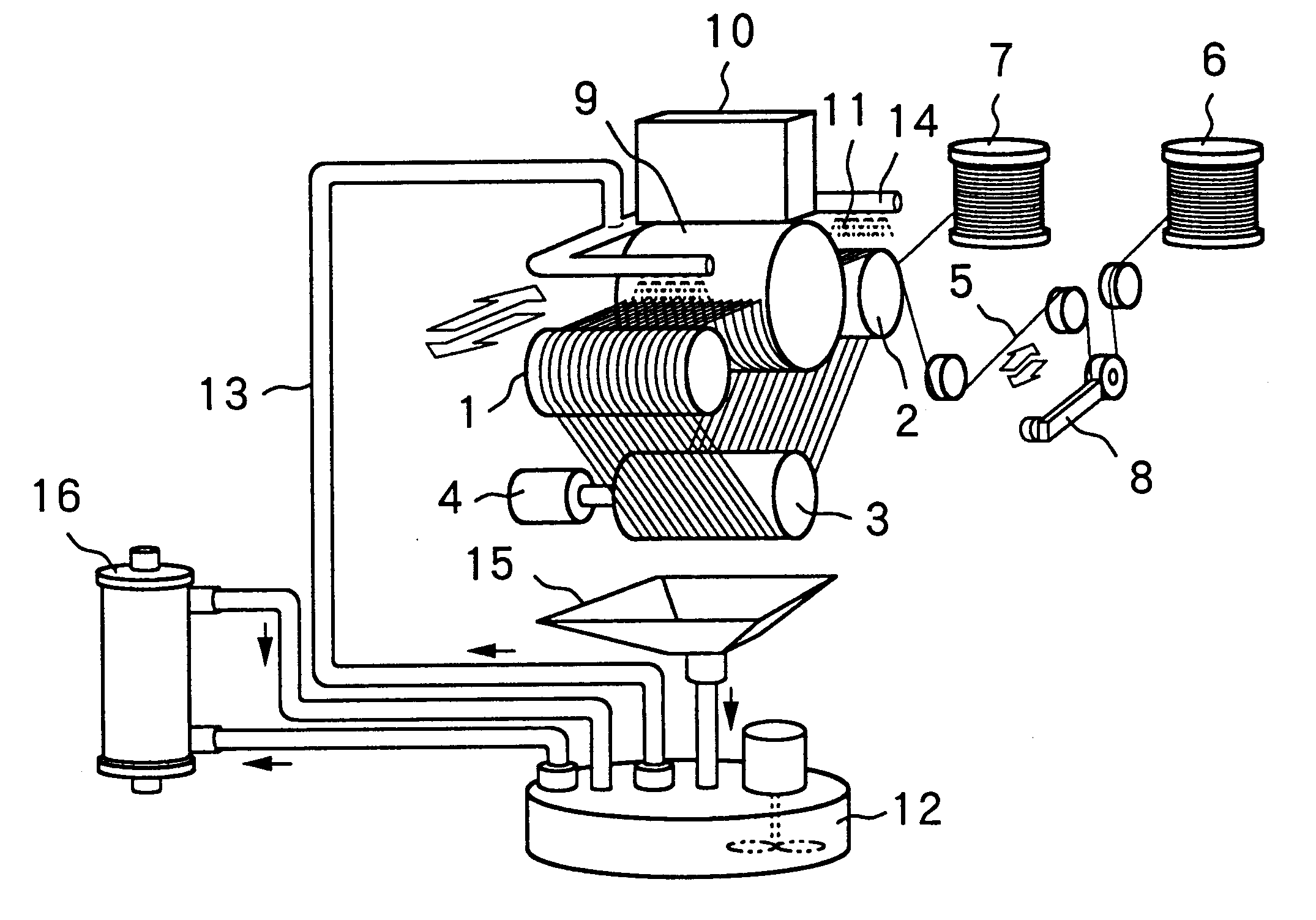
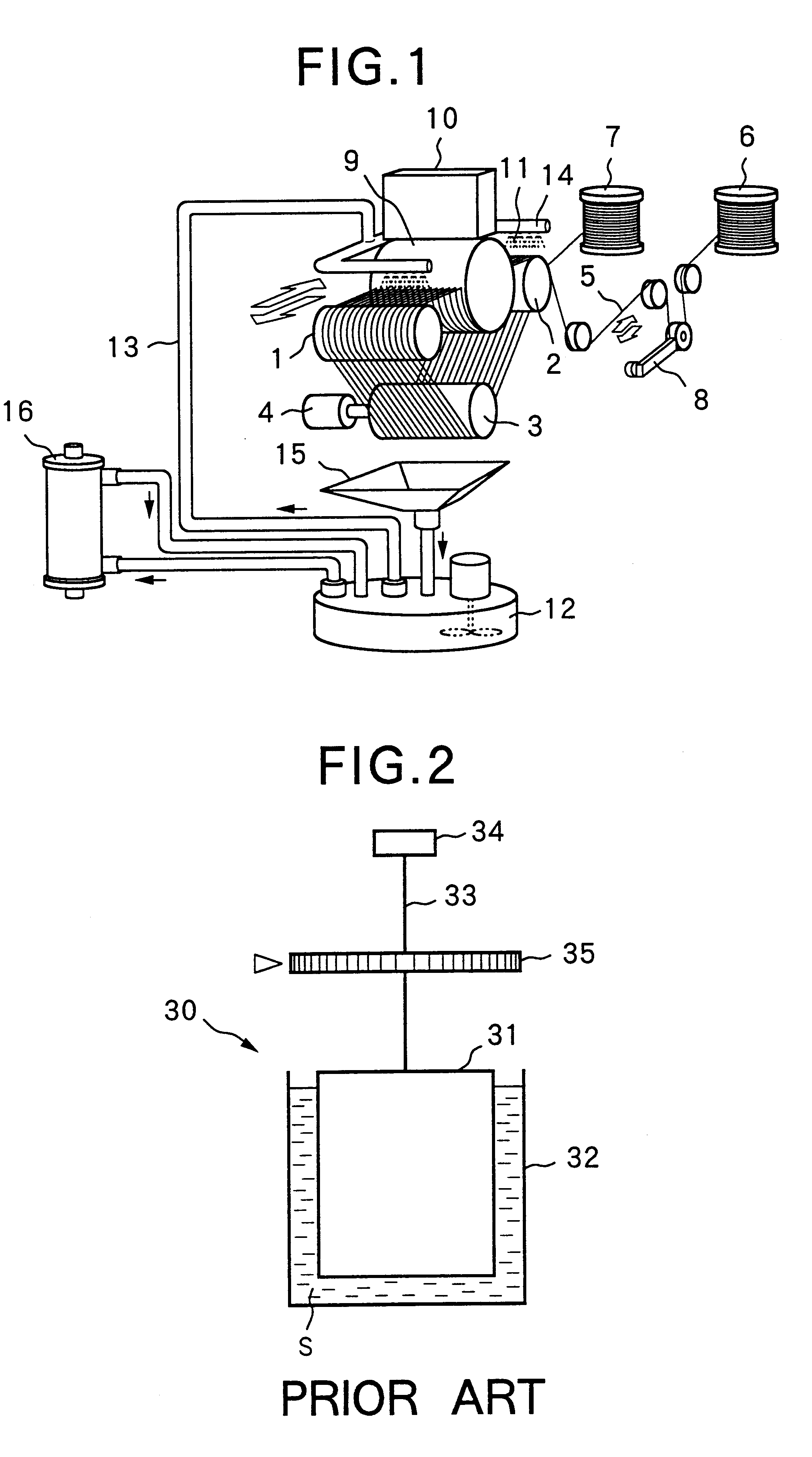
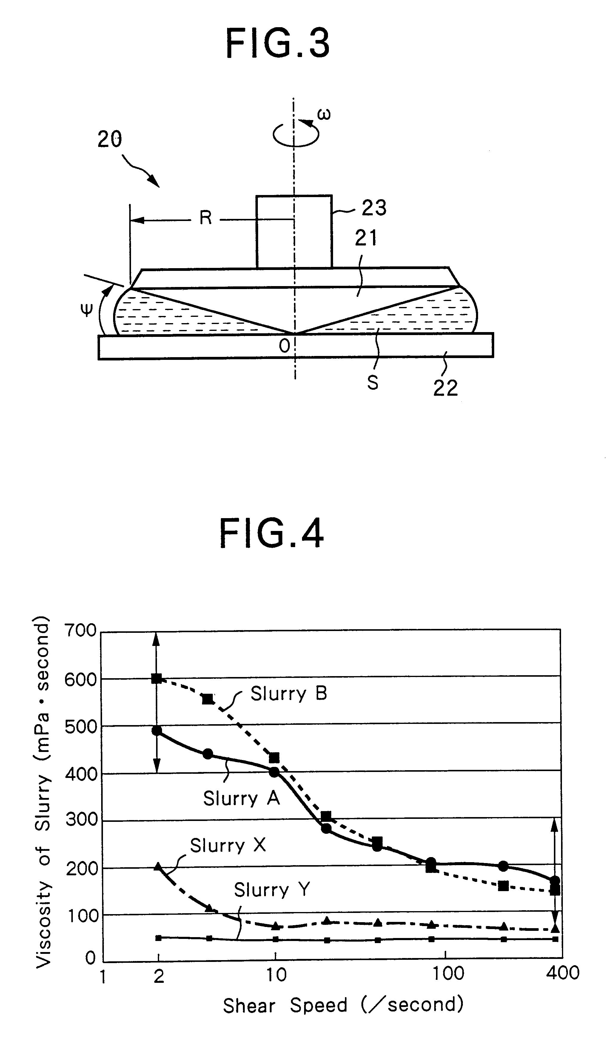
Four kinds of slurry A, B, X and Y were prepared to compositions shown in Table 1, included below and SiC grits were dispersed therein at a ratio of 50 wt. %.

Each slurry was evaluated according to the present invention. Each slurry A, B, X and Y was poured in a narrow space between a cone 21 and a disc 22 vessel of a cone and plate type viscometer 20 (Type-E viscometer), and its viscosity was measured at a shear speed of 2 / second, 4 / second, 10 / second, 20 / second, 40 / second, 80 / second, 200 / second and 380 / second, respectively. FIG. 4 shows measurement results in relationship with the shear speed. Viscosity of each slurry A and B was within a range of 400-700 mPa.multidot.second at a shear speed of 2 / second and within a range of 50-300 mPa.multidot.second at a shear speed of 380 / second. But, viscosity of each slurry X and Y did not fulfill these requisitions.

Each slurry A, B, X and Y was used for wire-saw slicing a silicon ingot 9 of 400 mm in diameter to wafers of 1.0 mm in average thi...


PUM

PropertyMeasurementUnit
Pressureaaaaaaaaaa
Pressureaaaaaaaaaa
Viscosityaaaaaaaaaa

Abstract

Slurry useful for wire-saw slicing has viscosity adjusted to 400-700 mPa.second at a shear speed of 2/second and of 50-300 mPa.second at a shear speed of 380/second. The viscosity of slurry is measured using a cone and plate type viscometer which can measure viscosity at different shear speeds. Since the slurry sufficiently flows into inner parts of grooves formed in an ingot and consumed for wire-saw slicing due to the viscosity controlled in response to the shear speed, the ingot can be efficiently sliced to wafers or discs.

Description

1. Field of the InventionThe present invention relates to slurry useful for wire-saw slicing a silicon ingot, a compound semiconductor block, a quartz block or the like, and also-relates to a method of evaluating such slurry.2. Brief Description of the Prior ArtAfter top and tail parts are cut off a silicon ingot produced by a pulling method or the like, the silicon ingot is processed in the steps of outer diameter grinding, orientation flat processing, etc., and then sliced to wafers of a predetermined thickness. Although a slicer equipped with an inner blade has been used so far for slicing the ingot, a wire-sawing machine using a piano wire is used for slicing a big-size ingot.As shown in FIG. 1, a conventional wire-sawing machine has generally three grooved rollers 1-3, one of which is coupled to a driving motor 4. A wire 5 is pulled out of a wire reel 6, wound several times around the grooved rollers 1-3, and led to another wire reel 7. A tension is applied to the wire 5 by a t...

Claims


Application Information

Patent Timeline
IPC IPC(8): B28D5/04B28D5/00B28D1/02G01N11/10G01N33/28G01N33/26G01N11/14B24B27/06B24B57/02
CPCB28D1/025B28D5/007B28D5/045G01N11/142G01N33/2894Y10T83/472Y02P70/10
Inventor OISHI, HIROSHIASAKAWA, KEIICHIROMATSUZAKI, JUNICHIASHIDA, AKIO
Owner SUPER SILICON KENKYUSHOKK
Why Eureka
Try Eureka