Driveshaft bearing assembly

a technology for bearings and driveshafts, applied in the direction of bearing unit rigid support, couplings, transportation and packaging, etc., can solve the problems of increasing the overall cost of the vehicle, affecting the service life of the vehicle, and affecting the overall performance of the vehicle, so as to eliminate the need for service or replacement

Inactive Publication Date: 2002-07-23
NEAPCO INTPROP HLDG LLC
View PDF25 Cites 49 Cited by
  • Summary
  • Abstract
  • Description
  • Claims
  • Application Information

AI Technical Summary

Benefits of technology

It is a second object of the invention to provide a driveshaft bearing assembly which provides for a relatively stiff connection of the shafts, segments or portions of a multi-piece vehicle driveshaft.
It is a third object of the invention to provide a driveshaft bearing assembly which has a relatively lightweight and unitized design.
It is a fourth object of the invention to provide a driveshaft bearing assembly which substantially eliminates the need for service or replacement of the center bearing.

Problems solved by technology

While these bearing assemblies allow for the desired communication of torque between portions or segments of the driveshaft and rotatably support the driveshaft, they suffer from some drawbacks.
For example and without limitation, the splined members are relatively difficult and expensive to machine and / or manufacture, and undesirably increase the overall cost of the vehicle.
Furthermore, the splined members are normally and relatively loosely connected due to inherent manufacturing tolerances and constraints.
This relatively loose connection causes the engaged splined members to undesirably "wobble" as the vehicle is driven, thereby creating imbalance within the driveshaft and producing undesirable noise and vibration harshness ("NVH") which is undesirably communicated into the passenger compartment.
Moreover, the relatively heavy splined members decrease the efficiency of the driveshaft and cause a significant amount of wear and fatigue of the center bearing.
As a result, the center bearing often requires service or replacement which eliminates the "factory-set" balance of the driveshaft and increases the likelihood and frequency of occurrence of NVH problems.

Method used


Image

  • Driveshaft bearing assembly
  • Driveshaft bearing assembly

Examples


Embodiment Construction

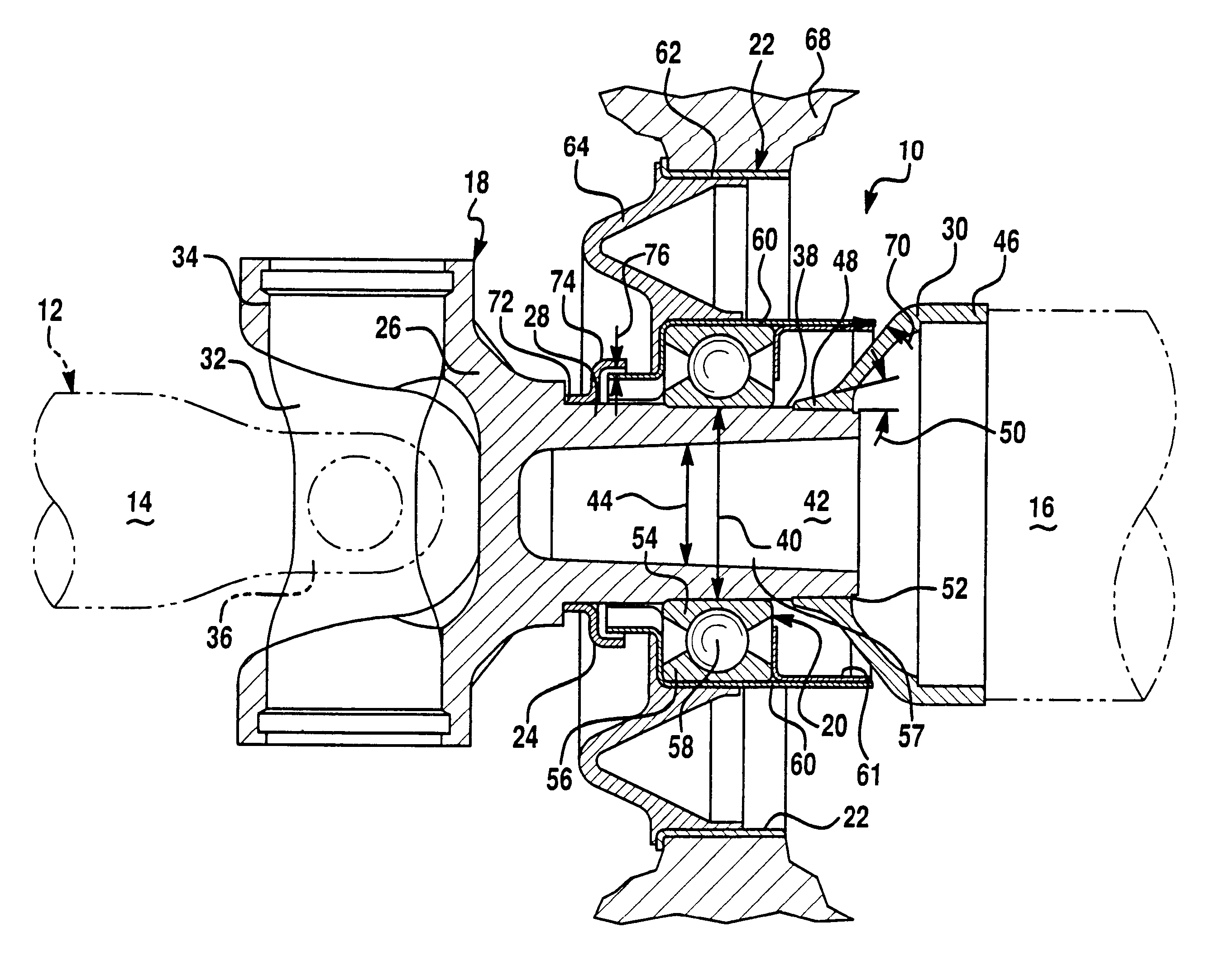
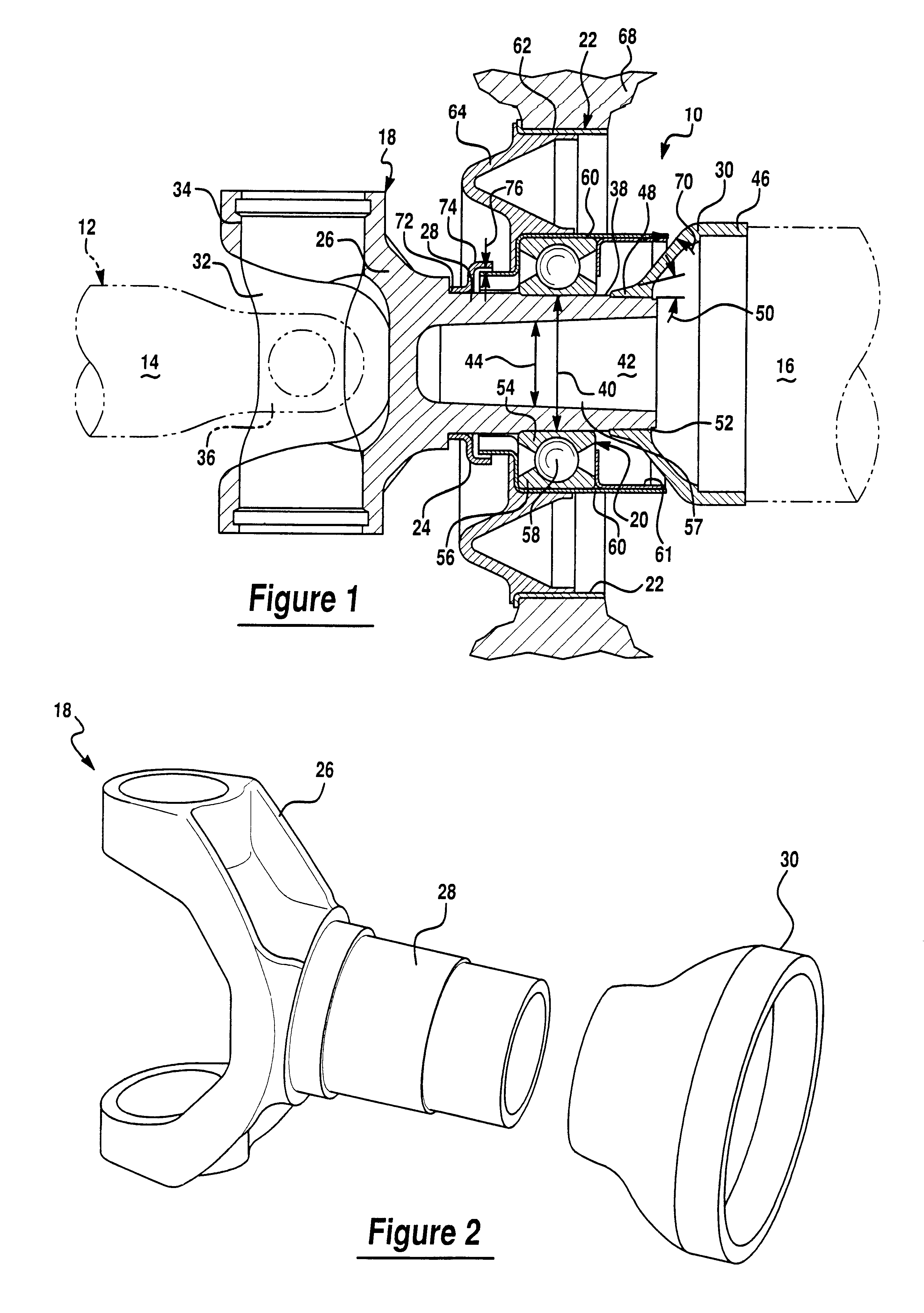
Referring now to FIGS. 1 and 2 , there is shown a driveshaft bearing and / or connecting assembly 10 which is made in accordance with the teachings of the preferred embodiment of the invention. Bearing assembly 10 is adapted for use in combination with a vehicle having a multi-piece driveshaft 12 including a first shaft, segment, or member 14 which is coupled to the vehicle's transmission (not shown) and a second shaft, segment or member 16 which is operatively coupled to the vehicle's differential (not shown). Bearing assembly 10 includes a "unitized" driveshaft connector or connecting member, yoke or rod 18, a generally circular or ring-shaped bearing member, assembly or apparatus 20, a bracket assembly 22, and a protective cover or shield member 24.

Connecting member 18 includes a yoke, member, or portion 26, a generally elongated cylindrical or tubular portion 28 which extends from yoke 26, and a generally conical collar, member, or portion 30, which is fixedly coupled to portion 2...


PUM


Abstract

A driveshaft bearing assembly 10 including a driveshaft connecting rod or member 18, a generally circular or ring-shaped bearing member, assembly or apparatus 20, a bracket assembly 22 and a protective cover or shield member 24. Bearing assembly 10 selectively connects and rotatably supports two members 14, 16 of a multi-piece driveshaft 12.

Description

(1) FIELD OF THE INVENTIONThis invention relates to a driveshaft bearing assembly and more particularly, to a driveshaft bearing assembly having a relatively light-weight, rigid and unitized design which provides for an improved overall balance of the driveshaft.(2) BACKGROUND OF THE INVENTIONA vehicle driveshaft is typically and operatively coupled to a transmission assembly and to a differential and operatively transfers the transmission produced torque to the differential, thereby causing the vehicle wheels to be desirably and selectively turned. One type of driveshaft, commonly referred to as a "multi-piece" driveshaft, includes multiple shafts, segments or members (e.g., two shafts) which are operatively connected together and which are rotatably supported by a driveshaft bearing assembly.These types of driveshaft bearing assemblies typically include a connecting assembly which operatively connects or links the two shafts or segments of the driveshaft and a "center" bearing mem...

Claims


Application Information

Patent Timeline
Patent Type & Authority Patents(United States)
IPC IPC(8): B60K17/22B60K17/24F16C33/76F16C35/077F16C35/04
CPCB60K17/24F16C33/76F16C35/077F16C19/06F16C27/066F16C33/80F16C2326/06
Inventor KELLY, FRANCIS X.PARKER, GARY KEITHGOLEMBIEWSKI, WALTER J
Owner NEAPCO INTPROP HLDG LLC
Why Eureka
Try Eureka