Sail battens
- Summary
- Abstract
- Description
- Claims
- Application Information
AI Technical Summary
Problems solved by technology
Method used
Image

Examples
Embodiment Construction
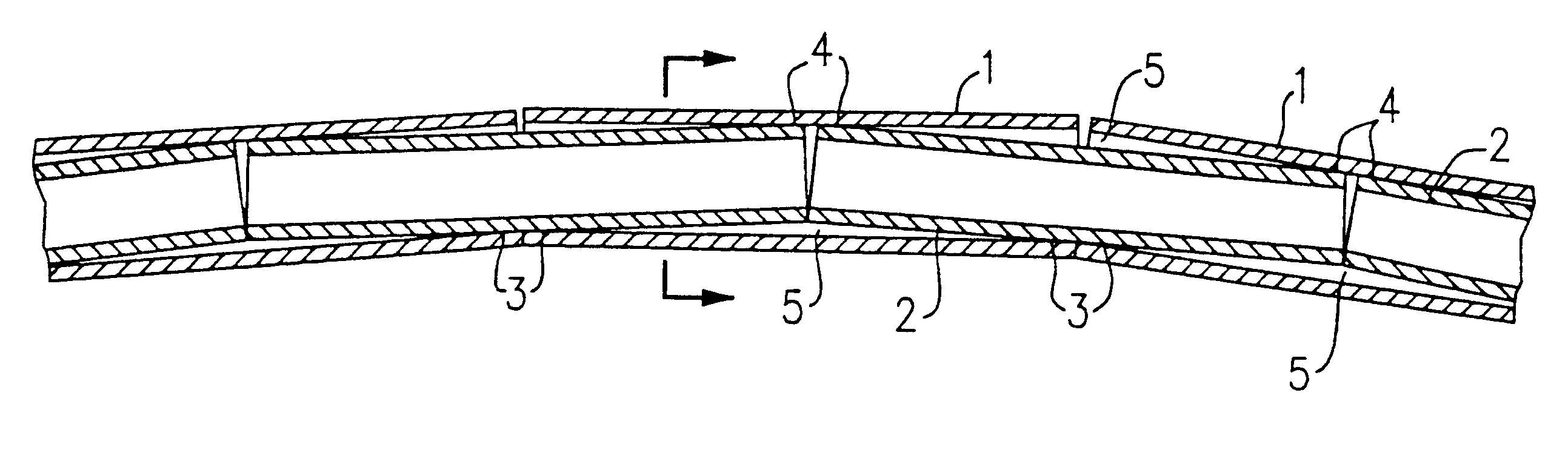
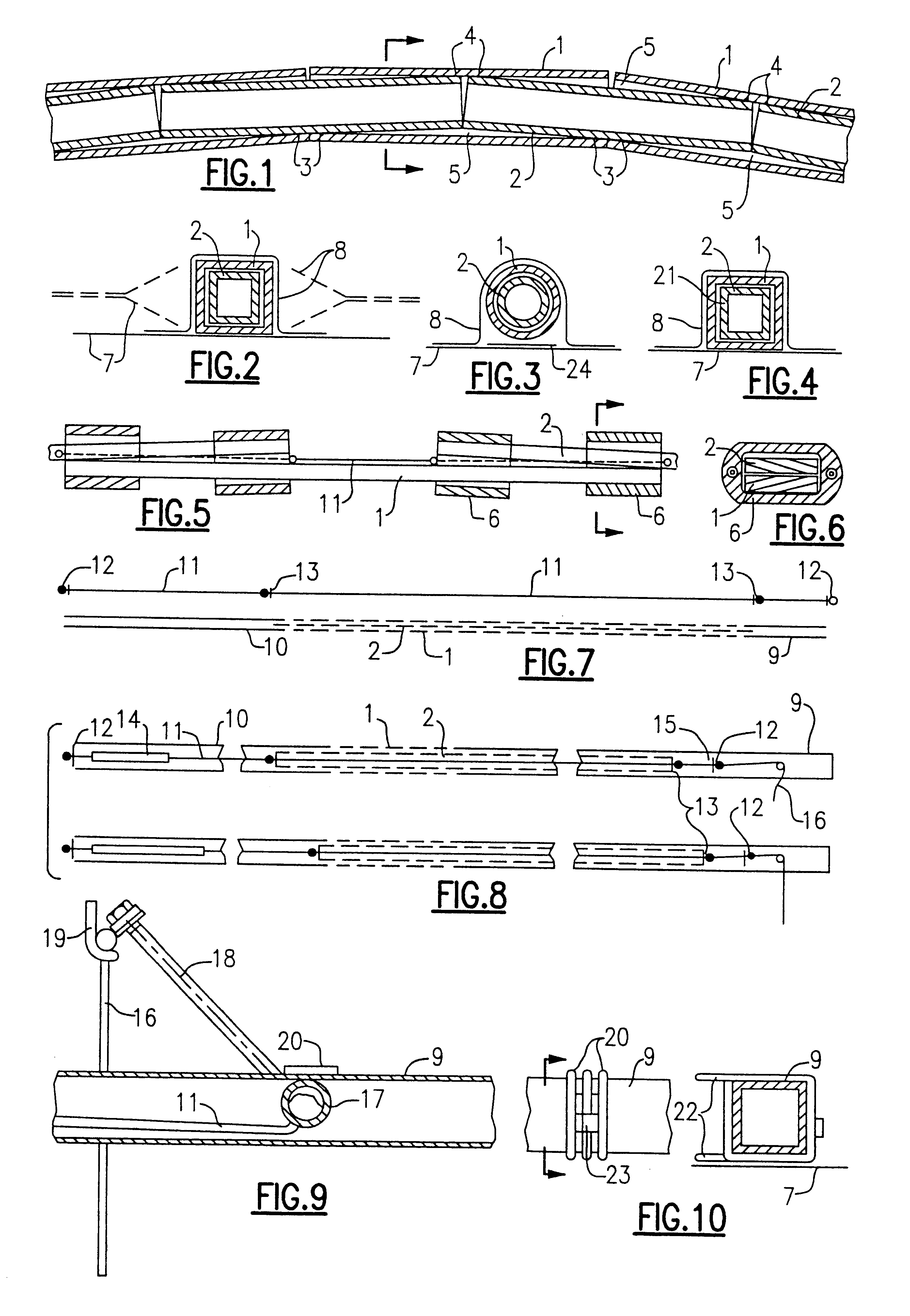
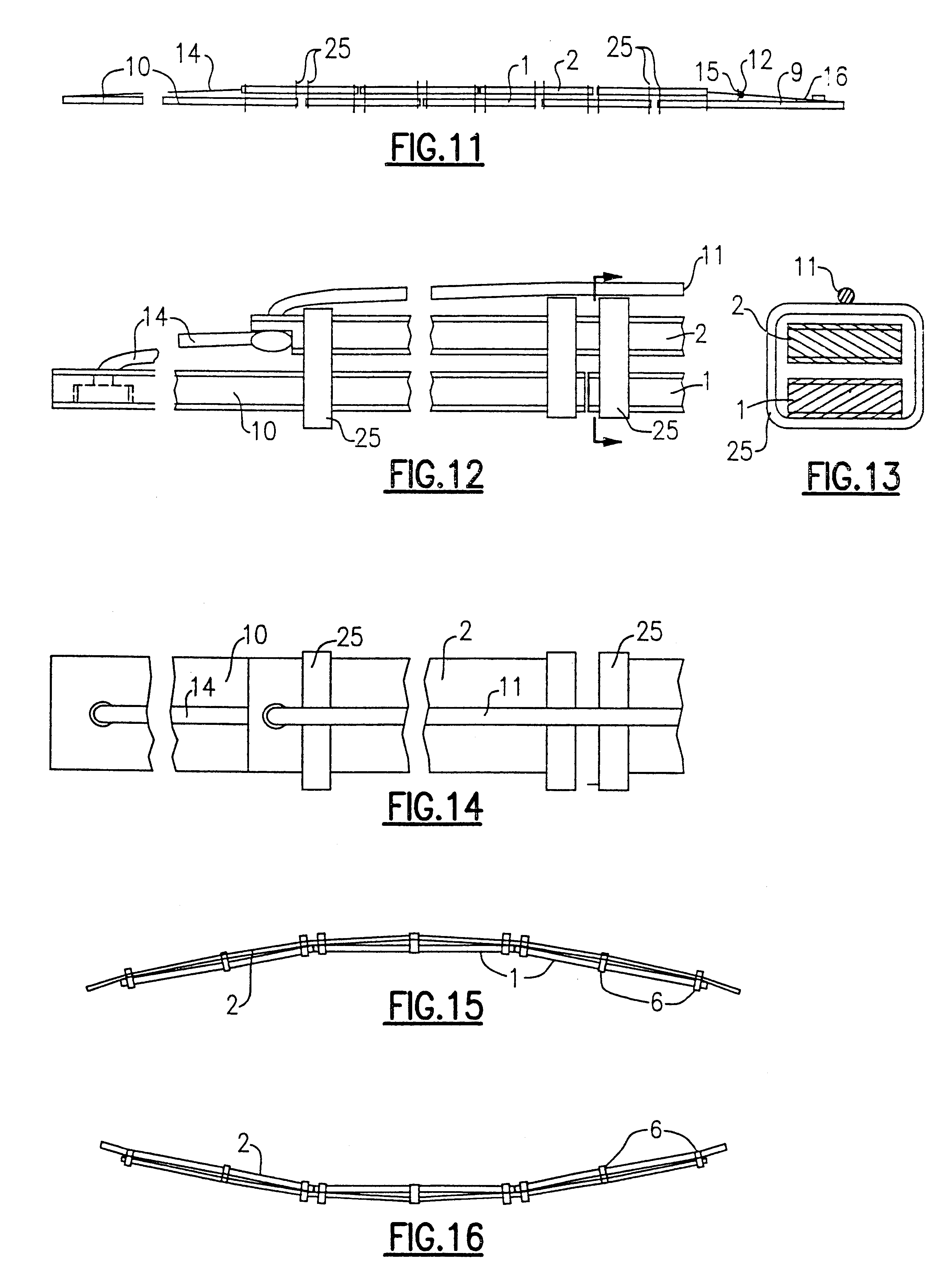
The aim is a reliable, lightweight and not too expensive sail batten, which gets into the desired curvature already at minimal winds and which then keeps this widely also at strong winds. This aim is achieved by the characterising features of the claims. So, according to claim 1, FIGS. 1 to 7, 15, 16, the batten forces caused by the wind forces remain small, because the battens are about 100 times as long as they are wide, and because this is used to get long lever arms: With a length Ls of the batten bar of 5% of the length L of the sail batten and with a length of the lever arm of half of the length of the respective batten bar or of the width B of the known batten joints it follows, that the forces at the inventive batten are less than the 0,5 B / 0,5 Ls=0.5.times.0.01 L / 0.5.times.0.05 L=0.2 fold, i.e. less than 20% of the value at the known constructions. Moreover, because of the large distance between the stops, the dimensional accuracy becomes less essential. Moreover, the usual...
PUM
 Abstract
Description
Claims
Application Information
 - R&D Engineer
- R&D Manager
- IP Professional
- Industry Leading Data Capabilities
- Powerful AI technology
- Patent DNA Extraction
Browse by: Latest US Patents, China's latest patents, Technical Efficacy Thesaurus, Application Domain, Technology Topic.
© 2024 PatSnap. All rights reserved.Legal|Privacy policy|Modern Slavery Act Transparency Statement|Sitemap