Universal cover plate

a universal cover and plate technology, applied in the field of cover plates, can solve the problems of unattractive wiring, time-consuming, expensive and inefficient, and the prior art therefore does not solve the problem

Inactive Publication Date: 2002-08-27
MICHAEL J SHOTEY +1
View PDF34 Cites 76 Cited by
  • Summary
  • Abstract
  • Description
  • Claims
  • Application Information

AI Technical Summary

Benefits of technology

According to the present invention, an electrical cover plate includes a base having a planar member. A first set of removable tabs is connected to the base so that removal of the first set of removable tabs forms a first set aperture, and a second set of removable tabs is connected to the base so that removal of the second set of removable tabs forms a second set aperture. The first set aperture and the second set aperture may each be bounded by an aperture periphery line so that the aperture periphery lines intersect. Also, the first tab set and th

Problems solved by technology

Cover plates enclose outlets behind a wall, thereby preventing inadvertent access to the electrically conductive elements of the outlets and hiding the unattractive wiring.
This is time-consuming, expensive and inefficient.
The prior art therefore does not so

Method used


Image

  • Universal cover plate
  • Universal cover plate
  • Universal cover plate

Examples


Embodiment Construction

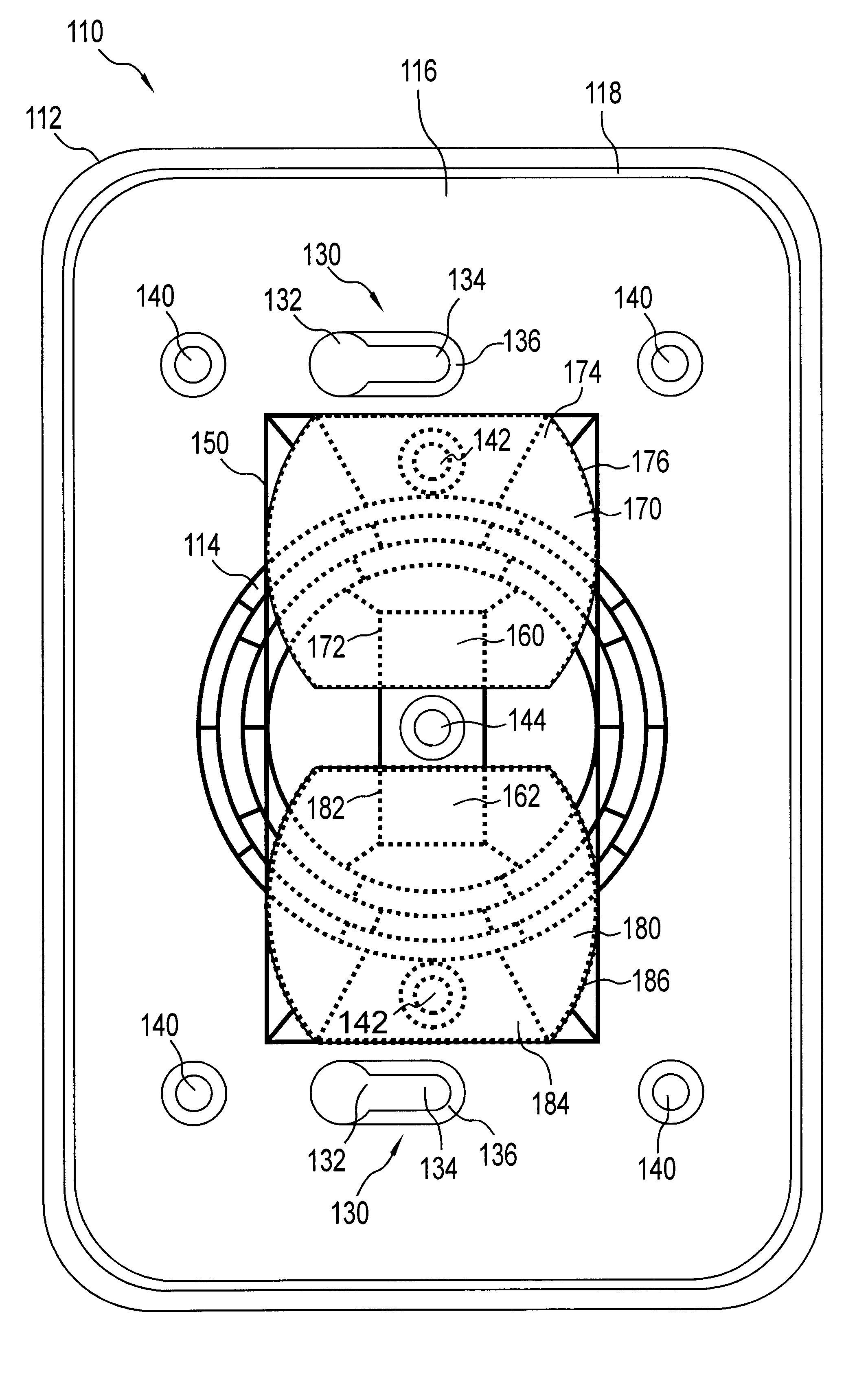
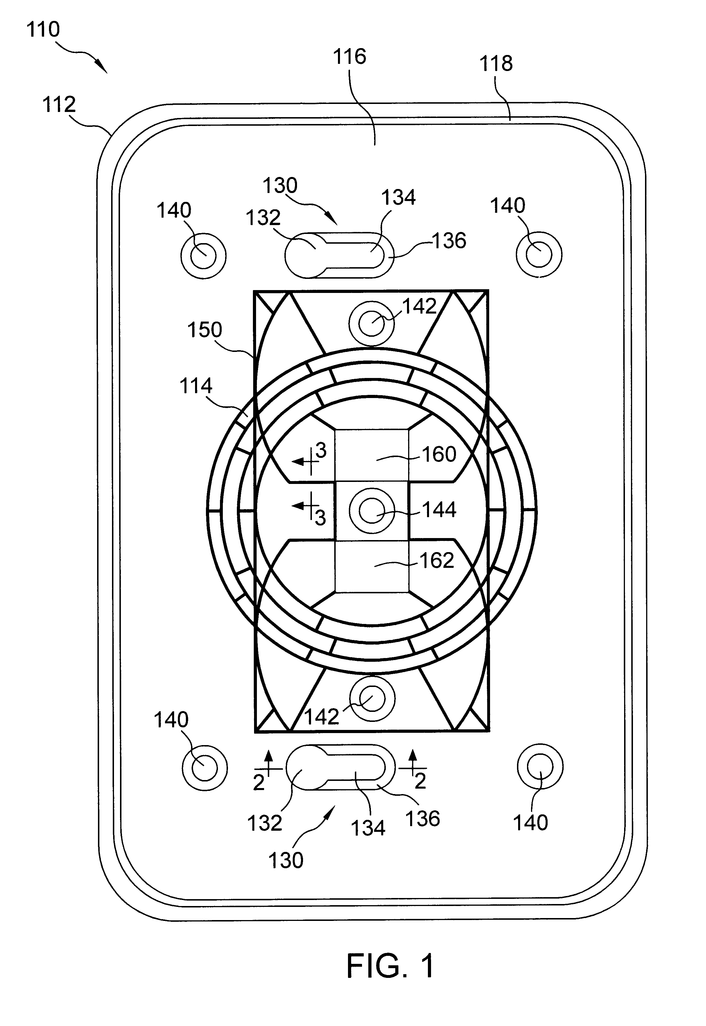
Referring to FIG. 1, a cover plate 110 includes a generally rectangular planar base 112 and plural removable tabs 114. Tabs 114 are preferably integral with base 112. However, they may be non-integral tabs such as snap-in tabs. A different set of tabs may be removed, such as by cutting, sawing, or prying, to produce each of a top duplex aperture, a bottom duplex aperture, a light switch aperture, and several different sizes of single round apertures. Each aperture is bounded by a corresponding aperture periphery line, and each set of tabs is bounded by a corresponding tab set periphery line. Unlike the embodiments of the '831 patent, the tab set periphery lines and the aperture periphery lines corresponding to different configurations intersect so that the areas of potential apertures overlap. In the embodiments of the '831 patent, potential aperture areas were nested within each other, but the aperture periphery lines did not intersect. The intersecting aperture periphery lines and...


PUM


Abstract

An electrical cover plate includes a base having a planar member. A first set of removable tabs is connected to the base so that removal of the first set of removable tabs forms a first set aperture, and a second set of removable tabs is connected to the base so that removal of the second set of removable tabs forms a second set aperture. The first set aperture and the second set aperture may each be bounded by an aperture periphery line so that the aperture periphery lines intersect. Also, the first tab set and the second tab set may have at least one tab in common, and each tab set may be bounded by a tab set periphery line so that the tab set periphery lines intersect. The tabs may be connected to the base by grooved connectors, connecting tabs, or other connections that removably connect the tabs to the base. The apertures may be shaped and positioned to receive a variety of specified electrical devices, such as round electrical sockets, duplex outlet sockets, ground-fault circuit interrupt sockets, or light switches.

Description

1. Technical FieldThis invention relates generally to a cover plate for electrical outlets, and more particularly to a universal cover plate that can be converted into a desired specific cover plate by detaching removable tabs.2. Background ArtCover plates enclose outlets behind a wall, thereby preventing inadvertent access to the electrically conductive elements of the outlets and hiding the unattractive wiring. The electrical devices attached at the outlet vary, and consequently cover plates of many varieties are known. For example, electric sockets, both standard and ground fault current interrupts; light switches, both toggle and rocker plates; and cable television or telephone ports may be wired at a given outlet. The outlets may be used for indoor or outdoor weatherproof wiring, or may require a locked cover.Each type of outlet has a different type of cover plate configured for it. To install or service the outlets, an electrician must carry several types of cover plates to ea...

Claims


Application Information

Patent Timeline
IPC IPC(8): H02G3/14
CPCH02G3/14
Inventor SHOTEY, MICHAEL J.SHOTEY, MARCUS J.MALTBY, EDGAR W.
Owner MICHAEL J SHOTEY
Why Eureka
Try Eureka