I-beam walk assist device

Inactive Publication Date: 2002-10-15
SMITH DONALD E
View PDF16 Cites 75 Cited by
  • Summary
  • Abstract
  • Description
  • Claims
  • Application Information

AI Technical Summary

Benefits of technology

It is thus an object of the invention to provide an I-beam walk assist device that includes first and second individually adjustable height I-beam support assemblies, an I-beam having a first beam end supported by the first adjustable height I-beam support assembly and a second I-beam end supported by the second adjustable height I-beam support assembly, a gantry crane rollably mounted onto the I-beam and rollable along a section of the I-beam, a first and a second user controlled I-beam support assembly height adjustment winch in mechanical connection, respectively, with one of the first or second individually adjustable height I-beam support assemblies, and a patient harness connecting mechanism in connection with the gantry crane and having attachment structures for attaching a patient support harness; the gantry crane including a rollable trolley supporting a user controllable electric patient support winch having a lift/lower control device that includes an extend/retract switch mechanism for allowing an operator to extend and retract a flexible support cable connected at one end to a winch spool of the user controllable electric patient support winch and in mechanical lifting connection with the patient harness connecting mechanism; each of the first and second individually adjustable height I-beam support assemblies including a horizontal support member, an outer vertical support tube extending upward from a top center of the horizontal support member and having a tubular passageway therein open at a top outside tube end thereof and an outer vertical support tube surface to which a guide tube with a guide tube passageway is rigidly attached, a

Problems solved by technology

It is often difficult for health care providers to provide the necessary lifting force to assist patients engaged in walking types of physical therapy because they do not have the physical strength to maintain the

Method used


Image

  • I-beam walk assist device
  • I-beam walk assist device
  • I-beam walk assist device

Examples


Embodiment Construction

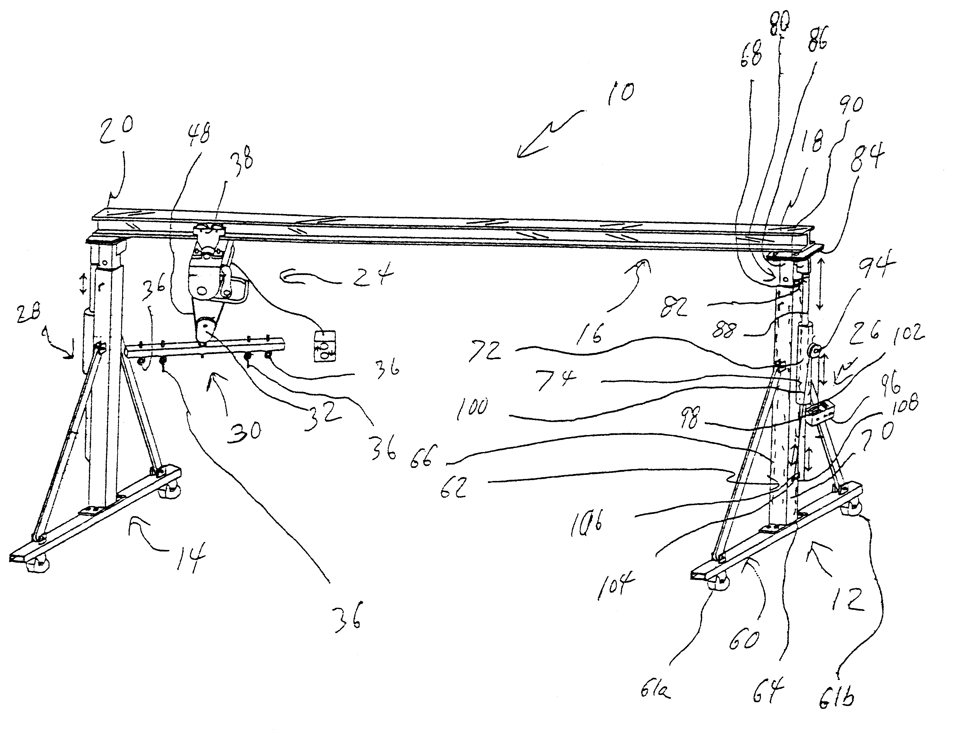
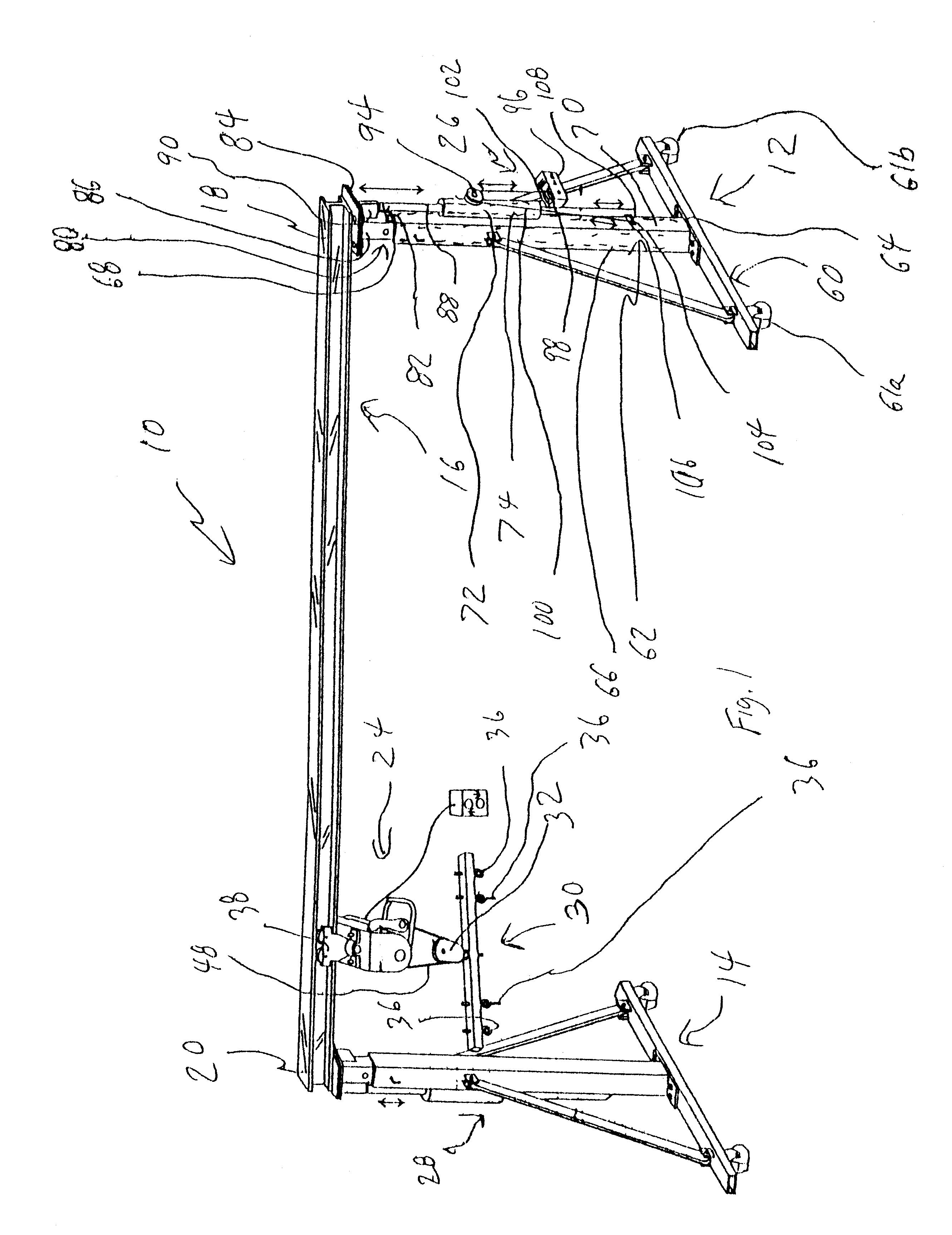
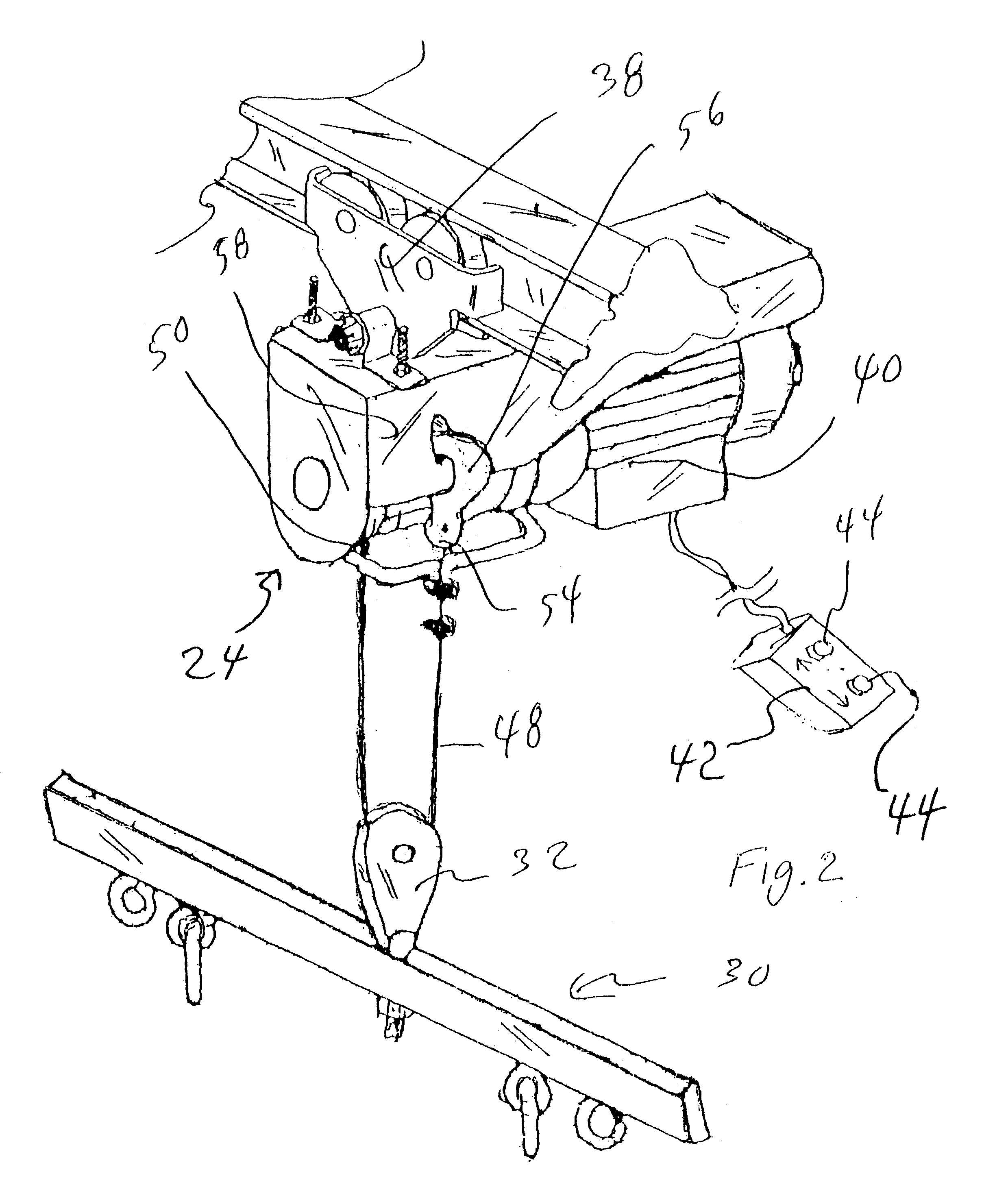
FIGS. 1 and 2 show various aspects of an exemplary embodiment of the I-beam walk assist device of the present invention generally designated 10. I-beam walk assist device includes first and second individually adjustable height I-beam support assemblies, generally designated 12,14; an I-beam, generally designated 16, having a first beam end 18 supported by the first adjustable height I-beam support assembly 12 and a second I-beam end 20 supported by the second adjustable height I-beam support assembly 14; a gantry crane, generally designated 24, rollably mounted onto I-beam 16 and rollable along a section of the I-beam 16 between first and second adjustable height I-beam support assemblies 12,14; identical first and second user controlled I-beam support assembly height adjustment winches 26,28 (winch 28 not shown) in mechanical connection, respectively, with one of the first or second individually adjustable height I-beam support assemblies 12,14; and a patient harness connecting me...


PUM


Abstract

A walk assist device including a mechanism for mechanically providing a lifting force to lift a patient from a seated position and provide a weight support force to a patient at an individually adjusted height level along the length of an exercise run.

Description

The present invention relates to rehabilitative exercise equipment and more particularly to an I-beam walk assist device that includes first and second individually adjustable height I-beam support assemblies, an I-beam having a first beam end supported by the first adjustable height I-beam support assembly and a second I-beam end supported by the second adjustable height I-beam support assembly, a gantry crane rollably mounted onto the I-beam and rollable along a section of the I-beam, a first and a second user controlled I-beam support assembly height adjustment winch in mechanical connection, respectively, with one of the first or second individually adjustable height I-beam support assemblies, and a patient harness connecting mechanism in connection with the gantry crane and having attachment structures for attaching a patient support harness; the gantry crane including a rollable trolley supporting a user controllable electric patient support winch having a lift / lower control d...

Claims


Application Information

Patent Timeline
IPC IPC(8): A61H3/00B66D3/00B66D3/18
CPCA61H3/008A61H3/04B66D3/18A61H2201/0192
Inventor SMITH, DONALD E.
Owner SMITH DONALD E
Why Eureka
Try Eureka