Tubing head control and pressure monitor device

a technology of pressure monitor and tubing head, which is applied in the direction of sealing/packing, drilling pipes, and wellbore/well accessories, etc., can solve the problem of unfavorable right angle bend of control tubing

Inactive Publication Date: 2002-10-29
ABB VETCOGRAY
View PDF10 Cites 36 Cited by
  • Summary
  • Abstract
  • Description
  • Claims
  • Application Information

AI Technical Summary

Problems solved by technology

For small bore tubing heads, this arrangement results i...

Method used


Image

  • Tubing head control and pressure monitor device
  • Tubing head control and pressure monitor device
  • Tubing head control and pressure monitor device

Examples


Embodiment Construction

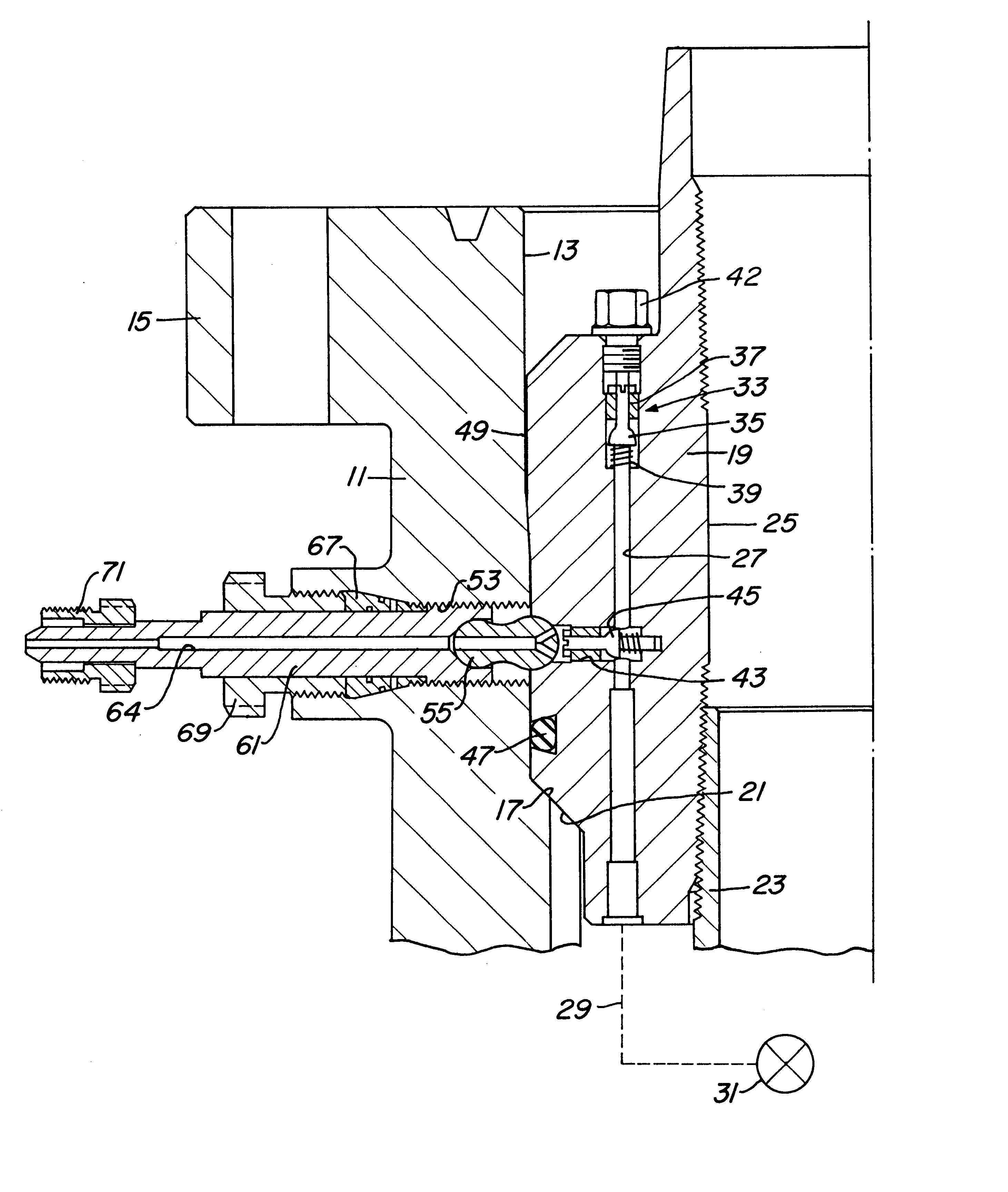
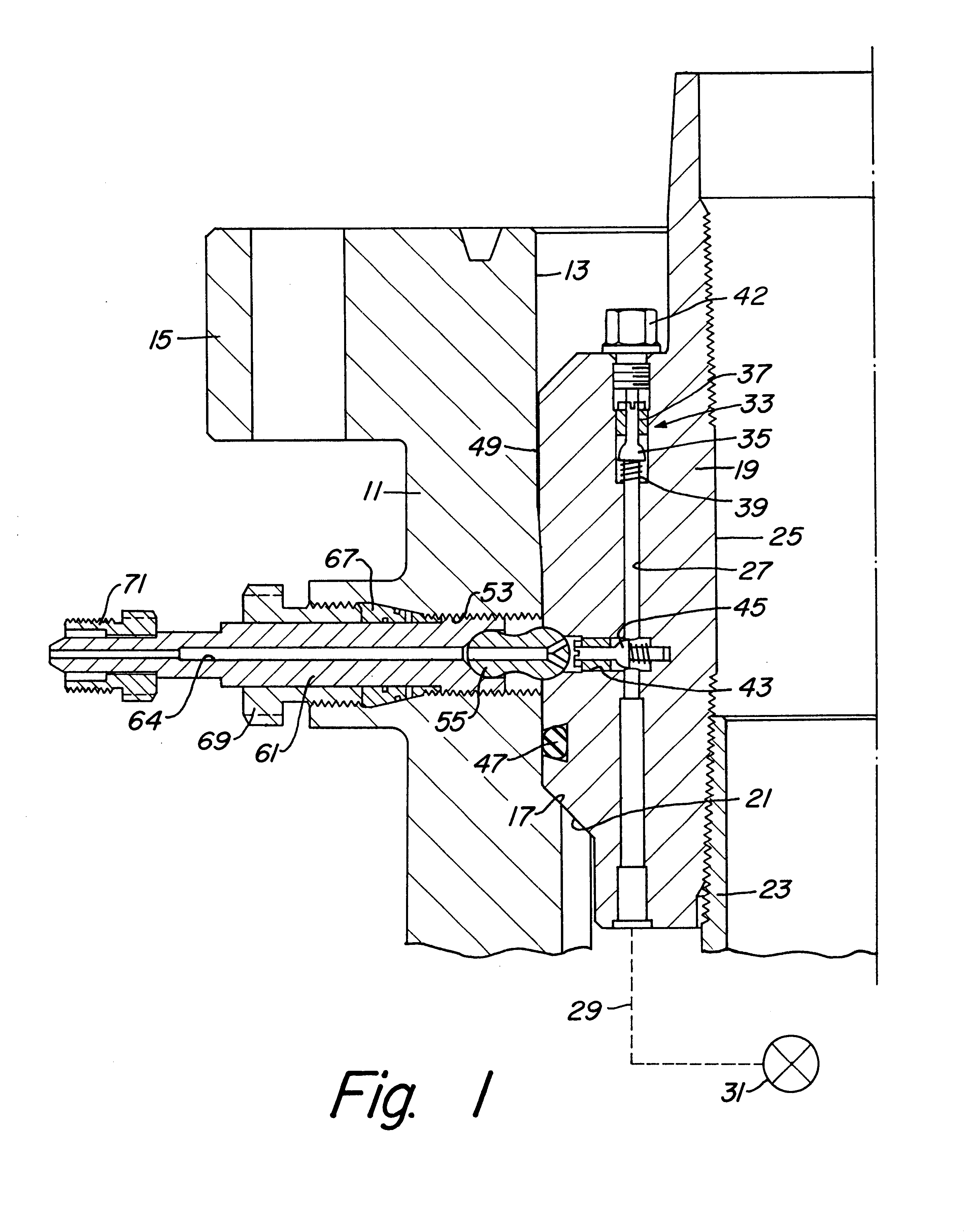
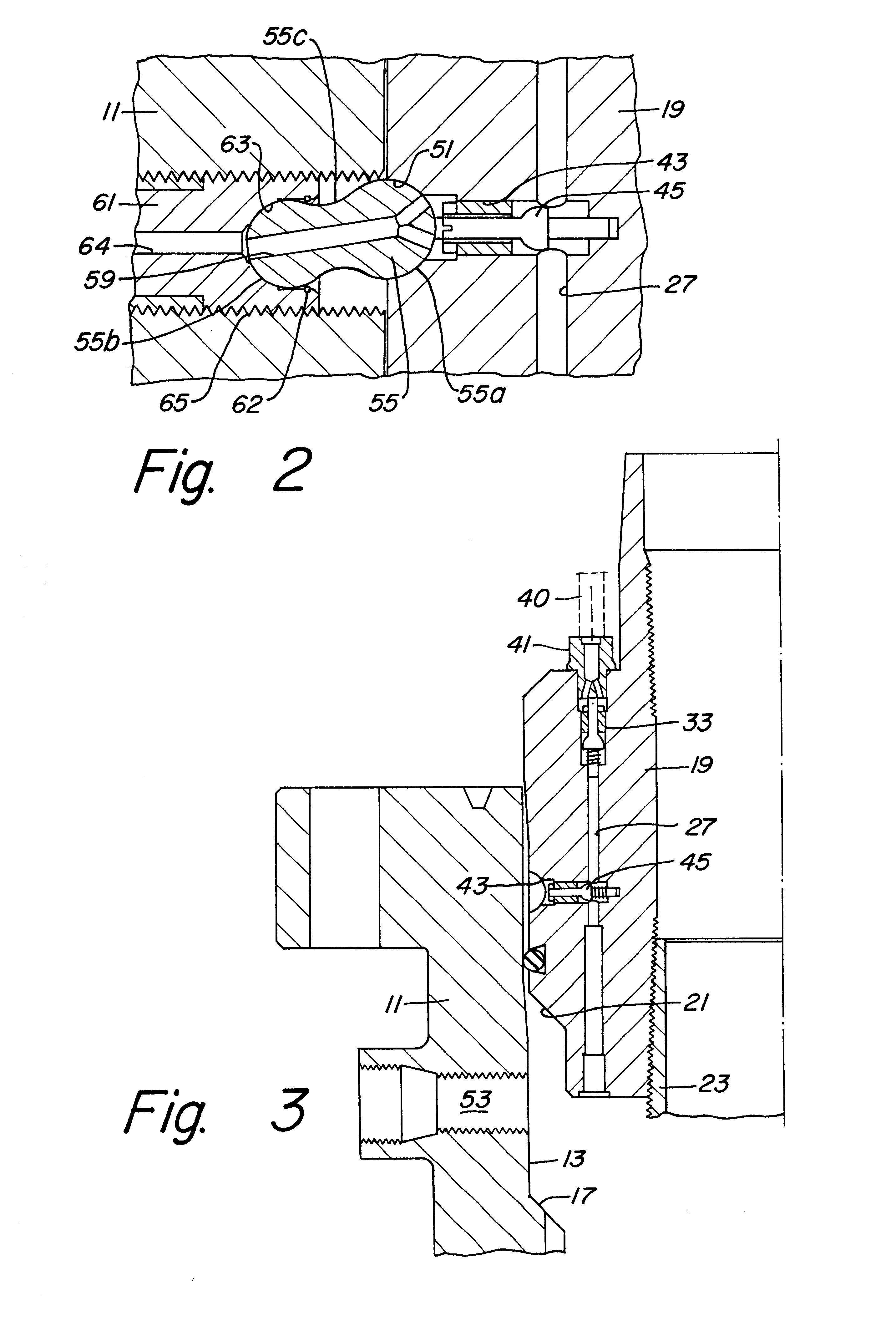
Referring to FIG. 1, wellhead housing or tubing head 11 is a located at the upper end of a well. Tubing head 11 has a bore 13. An external flange 15 on tubing head 11 allows connection to a bonnet or other tubular structure located above. Bore 13 has a conical load shoulder 17 formed therein.

In FIG. 1, a tubing hanger 19 is shown landed in bore 13. Tubing hanger 19 has a downward facing shoulder 21 that lands on load shoulder 17. A string of production tubing 23 secures to tubing hanger 19. Tubing hanger 19 has a bore 25 extending axially through it that registers with the interior of production tubing 23 for the production of well fluids.

Tubing hanger 19 has at least one axially extending passage 27 that extends through it. Typically there will be more than one. Each passage 27 extends parallel and offset to tubing hanger bore 25. A hydraulic line 29 secures to the lower end of passage 27. Line 29 extends down alongside tubing 23 and connects to a device that requires hydraulic flu...


PUM


Abstract

A tubing hanger and wellhead have features for controlling and monitoring fluid pressure to downhole equipment. The tubing hanger has an internal vertical passage. A hydraulic line connects to the lower end of the vertical passage and runs downhole. The vertical passage communicates with a lateral passage through the outer wall of the hanger. A lateral passage through the wellhead housing is generally aligned with the lateral passage of the hanger when the hanger is installed in the wellhead housing. A pressure shaft is installed in the wellhead passage and has a passage therethrough. A seal member having spherical ends is inserted between spherical receptacles located on the inner end of the pressure shaft passage and on the outer end of the lateral passage of the hanger. The seal member has an internal passage having a flared inner end. The seal member is allowed to rotate to sealingly connect the lateral passages if some misalignment of the lateral passages exists. A gage or other pressure monitoring device or a source of hydraulic pressure can be attached to the outer end of the pressure shaft to communicate with the shaft passage.

Description

1. Field of the InventionThis invention relates in general to wellhead assemblies and in particular to providing fluid pressure to a control line through connected passages in a tubing hanger and a wellhead housing.2. Description of the Prior ArtIn oil and gas wells where the wellhead is located at surface level, a tubing hanger will land within a tubing head. The-tubing hanger is located at the upper end of one or more strings of tubing through which production fluids will pass. A passage is typically provided in the tubing hanger to accommodate a control line that may be provided for control of a sub-surface safety valve or other downhole equipment. The valve must have fluid pressure applied to keep the valve open, and the pressure needs to be monitored to ensure the valve remains in an open position.In related art applications, a control line passage is formed in a tubing hanger and is substantially parallel to the longitudinal axis of the tubing hanger. For small bore tubing hea...

Claims


Application Information

Patent Timeline
IPC IPC(8): E21B34/02E21B33/03E21B34/00E21B33/04E21B33/00
CPCE21B33/04E21B34/02E21B2033/005E21B2200/01E21B34/025
Inventor BRIDGES, CHARLES D.
Owner ABB VETCOGRAY
Why Eureka
Try Eureka