Retrievable Tubing Hanger Installed Below Tree

a tubing hanger and tree technology, applied in the direction of drilling pipes, sealing/packing, borehole/well accessories, etc., can solve the problems of not being economical to utilize the same vessel, and systems typically do not have the ability to pull tubing

Inactive Publication Date: 2007-10-25
VETCO GRAY
View PDF25 Cites 39 Cited by
  • Summary
  • Abstract
  • Description
  • Claims
  • Application Information

AI Technical Summary

Benefits of technology

[0008]In the first embodiment, the tubing hanger is installed and the well completed before running the spool. The tree cap is installed in the spool at the surface and the assembly is lowered together onto the wellhead housing. In the second embodiment, the operator installs the spool before drilling out through the wellhead housing. The drilling riser is coupled to the spool and the well is drilled to total depth through the spool. After reaching total depth, the operator runs the tubing through the spool and completes the well. Then the tree cap is installed.
[0009]In both embodiments, the tree cap may be retrieved from the spool for pulling the tubing through the tree for workover operations. Also, in the preferred embodiment, the tree cap has a flange that lands on the rim of the spool and a mandrel that protrudes above the spool. The mandrel has an external profile for attaching workover pressure control equipment to the tree cap.

Problems solved by technology

It may not be economical to utilize the same vessel that drilled the well to complete the well and install the tree.
Designs for trees that can be run on a lift line are known, but these systems typically do not have the ability to pull the tubing without disturbing the connection between the tree and the wellhead housing.

Method used


Image

  • Retrievable Tubing Hanger Installed Below Tree
  • Retrievable Tubing Hanger Installed Below Tree
  • Retrievable Tubing Hanger Installed Below Tree

Examples


Embodiment Construction

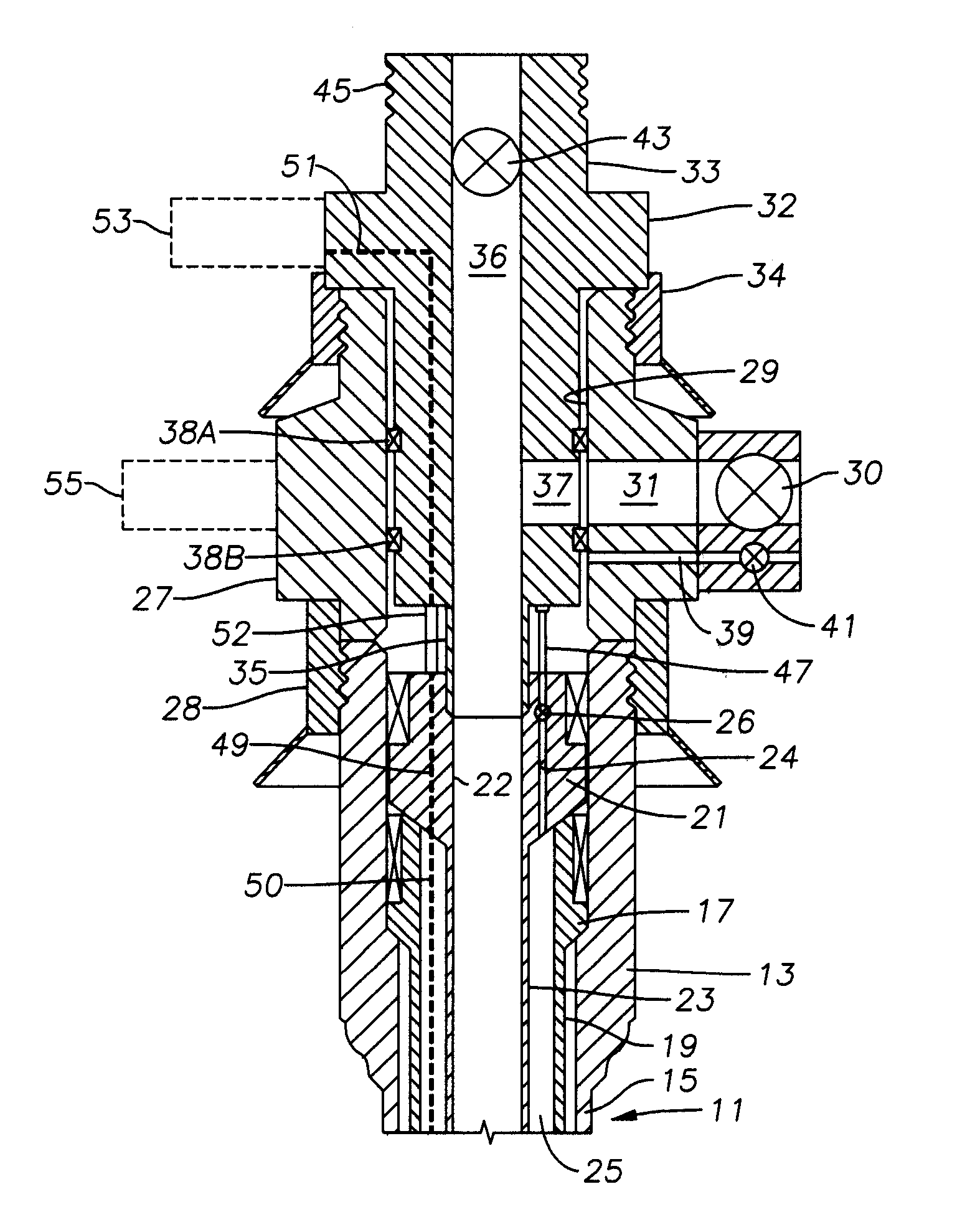
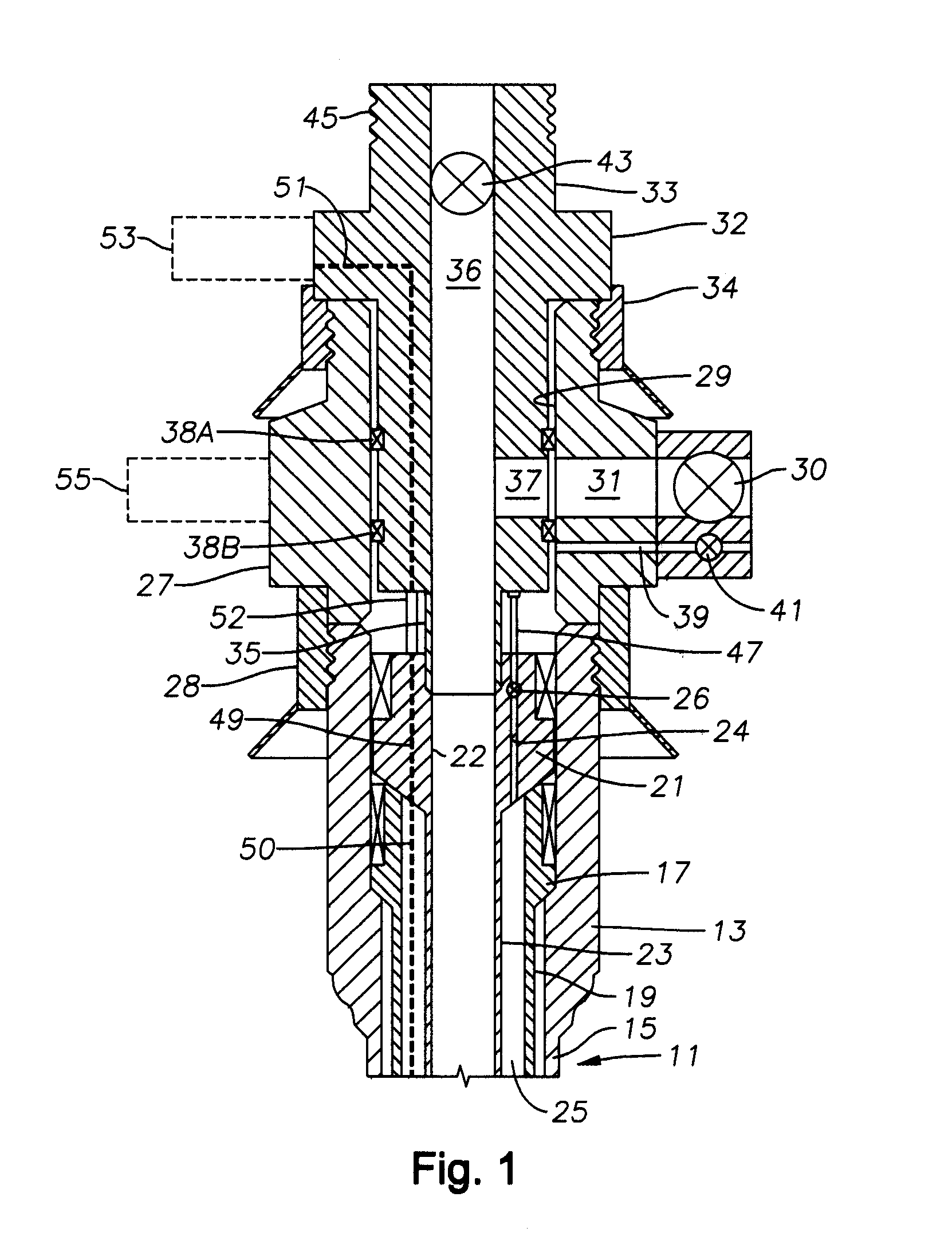
[0014]FIG. 1 shows a completed subsea wellhead assembly in accordance with both methods. A subsea well 11 has a wellhead housing 13 with a conductor casing 15 extending therefrom to a predetermined depth within the subsea well. A casing hanger 17 is landed within wellhead housing 13 with a string of casing 19 extending therefrom to another predetermined depth within subsea well 11.

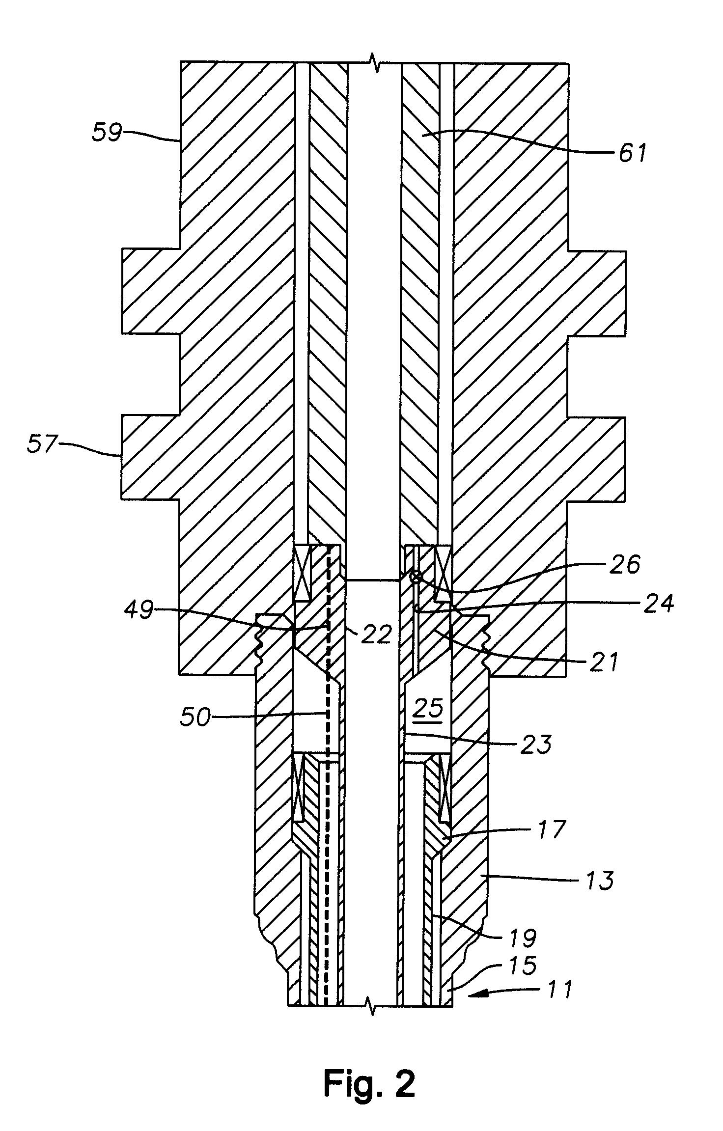
[0015]A tubing hanger 21 is landed within wellhead housing 13, with a string of tubing 23 extending therefrom within string of casing 19. In the preferred embodiment, tubing 23 extends to a production depth such that tubing 23 receives well fluid from within subsea well 11. Tubing hanger 21 has an axially extending production flow passage 33. A tubing annulus 25 is defined between the interior surface of string of casing 19 and the exterior surface of string of tubing 23. Tubing hanger 21 optionally may have a tubing annulus passage 24 extending axially through it offset from and parallel to production flo...


PUM


Abstract

A subsea wellhead assembly has a tubing hanger landed in a wellhead housing. A spool lands on the wellhead housing and has a bore with a laterally extending production flow outlet. A tree cap having an axially extending flow passage and a laterally extending production flow outlet lands within the bore of the spool. Upper and lower seals on the tree cap seal between the tree cap and the bore of the spool above and below the production flow outlet of the spool. An isolation tube on a lower end of the tree cap sealingly engages the production flow passage of the tubing hanger. The tree cap may be ran with the spool as an assembly and retrieved from the spool for workover operations.

Description

CROSS-REFERENCE TO RELATED APPLICATION[0001]This application claims priority to provisional application 60 / 793,467, filed Apr. 20, 2006.FIELD OF THE INVENTION[0002]This invention relates generally to a subsea wellhead assemblies, and more particularly to a configuration with a tubing hanger landed in a subsea wellhead housing, a spool with a lateral flow outlet and control valves landed on the wellhead housing, and wherein the tubing hanger is retrievable without removing the spool.BACKGROUND OF THE INVENTION[0003]A subsea well typically has a wellhead housing located on the sea floor. One or more casing hangers are supported in the wellhead housing, each located at the upper end of a string of casing. In one type of wellhead assembly, a tubing hanger located at the upper end of a string of tubing is installed in the wellhead housing. The operator may perforate the well at that point and install a wire line plug in the production passage of the tubing hanger. The operator then lands...

Claims


Application Information

Patent Timeline
Patent Type & Authority Applications(United States)
IPC IPC(8): E21B34/04
CPCE21B33/035E21B33/043E21B33/04
Inventor FENTON, STEVE P.
Owner VETCO GRAY
Why Eureka
Try Eureka