Apparatus and Method for Removing Subsea Structures

a technology for subsea structures and apparatuses, applied in the direction of manufacturing tools, sealing/packing, borehole/well accessories, etc., can solve the problems of high cost, considerable fatigue and risk for the operating personnel, and tiresome operations

Inactive Publication Date: 2009-10-29
BARRA MARC T +3
View PDF29 Cites 78 Cited by
  • Summary
  • Abstract
  • Description
  • Claims
  • Application Information

AI Technical Summary

Benefits of technology

[0007]The foregoing objects, features and advantages of the present invention, as well as others, will be more fully understood and better appreciated by reference to the following drawings, specification and claims.

Problems solved by technology

Clearly such operations are tiresome, expensive and involve considerable fatigue and risk for the operating personnel.

Method used


Image

  • Apparatus and Method for Removing Subsea Structures
  • Apparatus and Method for Removing Subsea Structures
  • Apparatus and Method for Removing Subsea Structures

Examples


Embodiment Construction

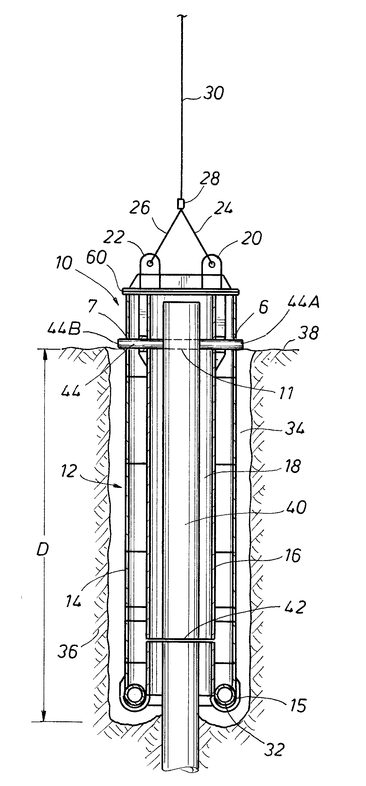
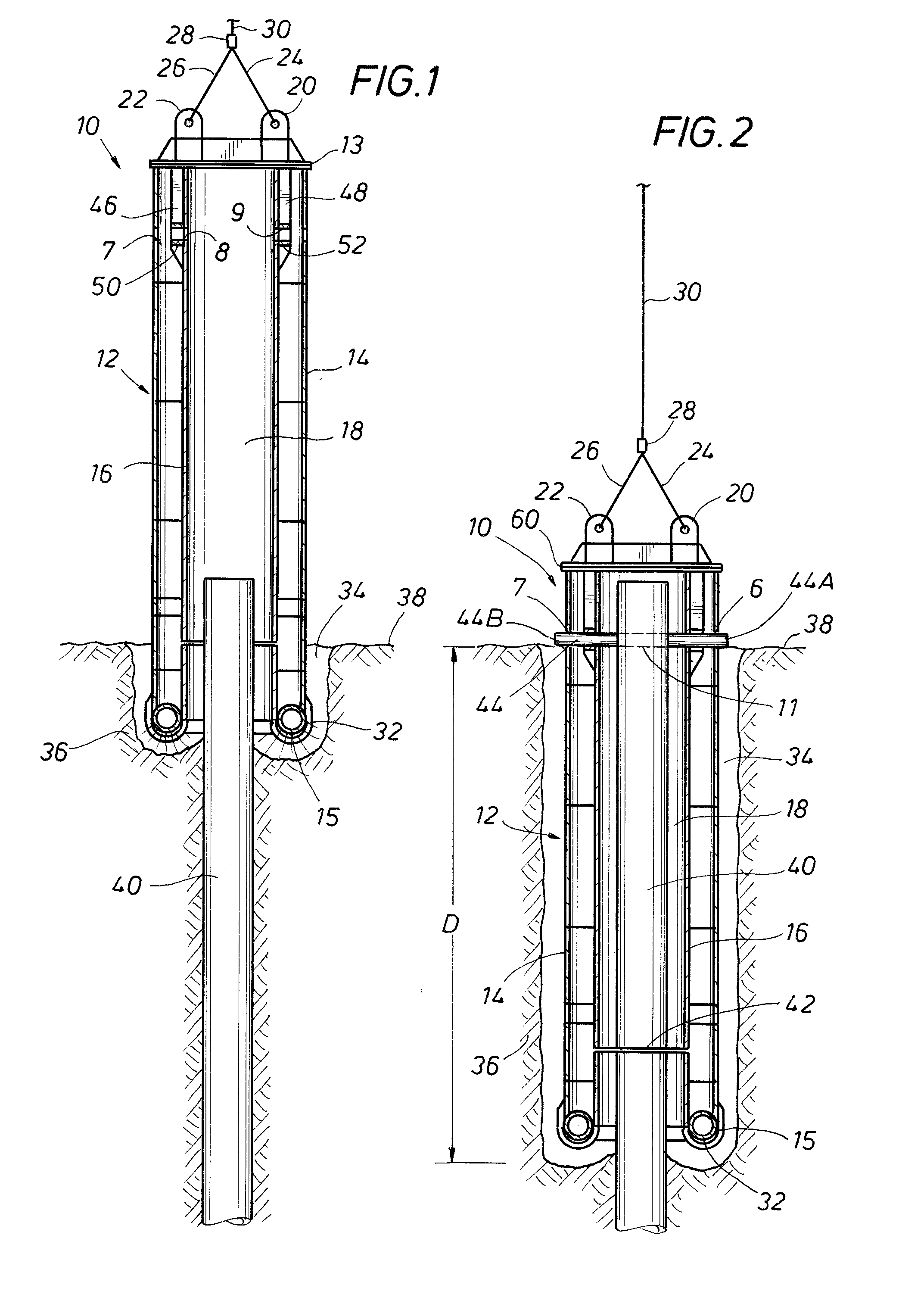
[0015]As used herein, the terminology “subsea structure,”“underwater structure” or similar terms refers to any type of structure being oil and / or gas well related or not which has at least a portion extending below the surface of the subsea soil, i.e., the “mudline.” Thus, the subsea structure can be a piling, a wellhead assembly, a casing stub or any number of structures. Generally the subsea structures which can be severed and / or removed by the apparatus and method of the present invention are of a generally tubular nature where tubular is not intended to mean a pipe but can mean a solid tubular member and whereas tubular member is not intended to mean a substantially cylindrical member in cross-section as opposed to an elongate structure having some protrusions as, for example, in a wellhead assembly. Additionally, the term subsea structure is not intended to be limited to a structure made of a single material, e.g., metal, wood, etc., but rather includes composite structures, e....


PUM

PropertyMeasurementUnit
depthaaaaaaaaaa
depthaaaaaaaaaa
movementaaaaaaaaaa

Abstract

An apparatus and method for removing a subsea structure wherein a housing defining a subsea structure receiving space and having a jetting system attached at or near the bottom of the housing is used to form an excavation around the subsea structure to the desired depth and a frame attached to or mounted in the housing carries a cutter assembly which is movable from a first position on the frame to a second position on the frame, the first position being on one side of the subsea structure, the second position being on the opposite side of the subsea structure.

Description

FIELD OF THE INVENTION[0001]The present invention relates to the removal of subsea structures extending below the sea bed.BACKGROUND OF THE INVENTION[0002]There are thousands of subsea structures connected with the drilling and production of oil and gas from oil and gas wells which are now characterized as abandoned. Non-limiting examples of such subsea structures include wellheads, casing stubs, etc., which either extend above the mudline (seabed) or are close to the mudline. The subsea structures can vary from simply a relatively large diameter piece of pipe to more complex structures comprised of concentric steel pipes, the annulus between which are filled with concrete or cement.[0003]Federal guidelines for the removal of such subsea structures in offshore water under United States jurisdiction typically mandate that the structure must be cut off 15 feet below the mudline unless a variance is obtained. Typical methods of removing subsea structures include explosive removal, ther...

Claims


Application Information

Patent Timeline
Patent Type & Authority Applications(United States)
IPC IPC(8): E21B29/12
CPCE21B19/002E21B29/00B23D57/0084B23D57/0007E21B29/12
Inventor BARRA, MARC T.PARKER, III, JAMES L.ALBORADO, ADAM C.CHAMPAGNE, III, ROBERT M.
Owner BARRA MARC T
Why Eureka
Try Eureka