Tubing annulus communication for vertical flow subsea well

a technology of tubing annulus and subsea well, which is applied in the direction of underwater drilling, drilling machines and methods, and wellbore/well accessories. it can solve the problems of leakage in one of the strings of casing or tubing, compromising the structural and pressure integrity of the well, and not enough space for the tubing annulus passag

Inactive Publication Date: 2005-06-07
VETCO GRAY
View PDF11 Cites 36 Cited by
  • Summary
  • Abstract
  • Description
  • Claims
  • Application Information

AI Technical Summary

Problems solved by technology

If pressure increased within the production tubing annulus, it would indicate that a leak exists in one of the strings of casing or in the tubing.
Regardless of where the leak is coming from, pressure build up in the production tubing annulus could collapse a portion of the production tubing, compromising the structural and pressure integrity of the well.
In small diameter tubing hangers, there may not be enough space for the tubing annulus passage.

Method used


Image

  • Tubing annulus communication for vertical flow subsea well
  • Tubing annulus communication for vertical flow subsea well
  • Tubing annulus communication for vertical flow subsea well

Examples


Embodiment Construction

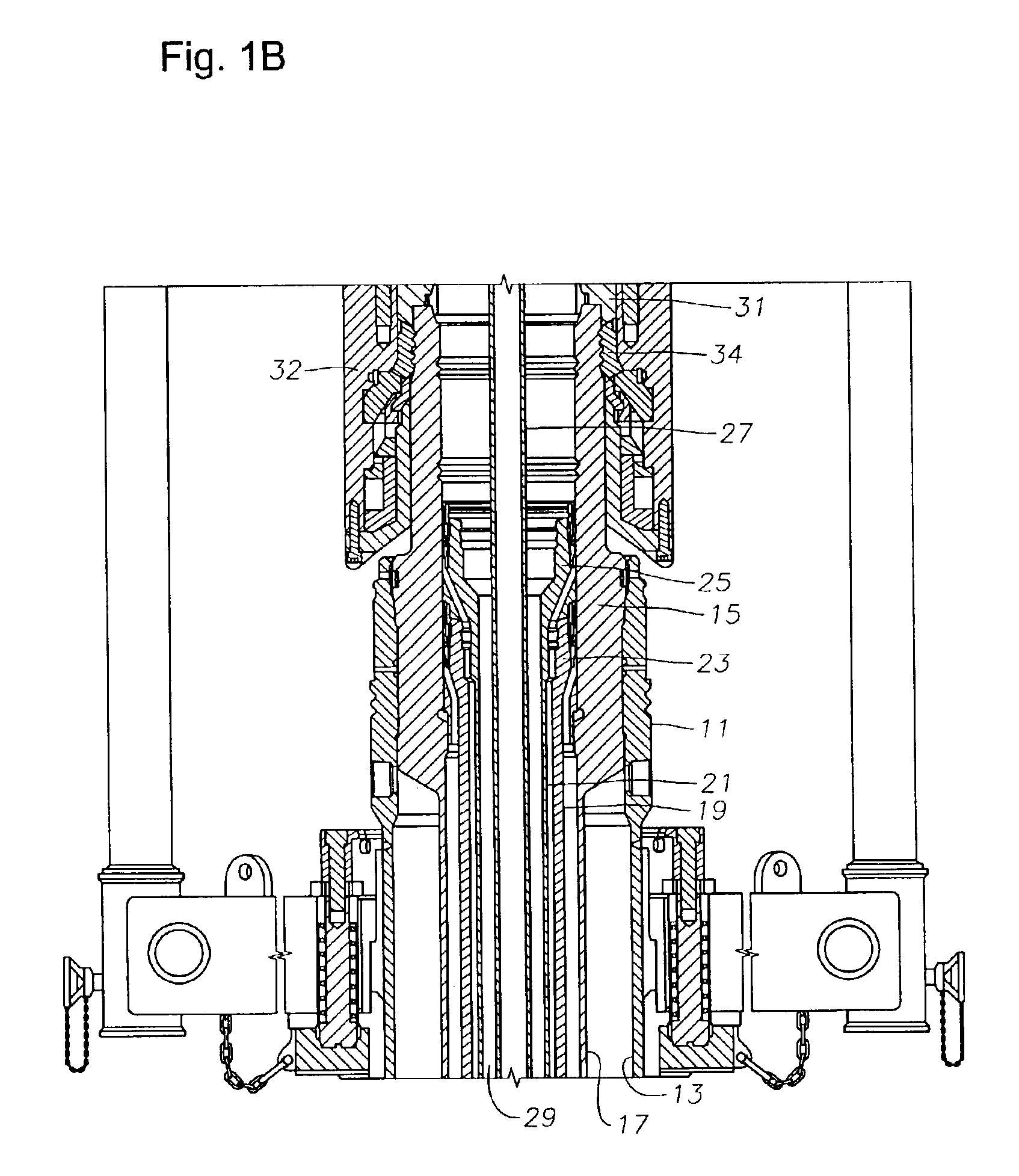
[0020]Referring to FIG. 1B, an outer or low pressure wellhead housing 11 is located at the sea floor. A large diameter pipe or conductor 13 extends into the well to the first depth. An inner or high pressure housing 15 lands in outer wellhead housing 11. High pressure wellhead housing or tubular wellhead member 15 has a large diameter string of casing 17 that extends into the well to a second depth and is cemented in place. In this well, there are two strings of casing 17 and 19, each extending to a greater depth. Each string of casing, 19, 21 is supported by a casing hanger 23, 25, respectively, within the bore of inner wellhead housing 15.

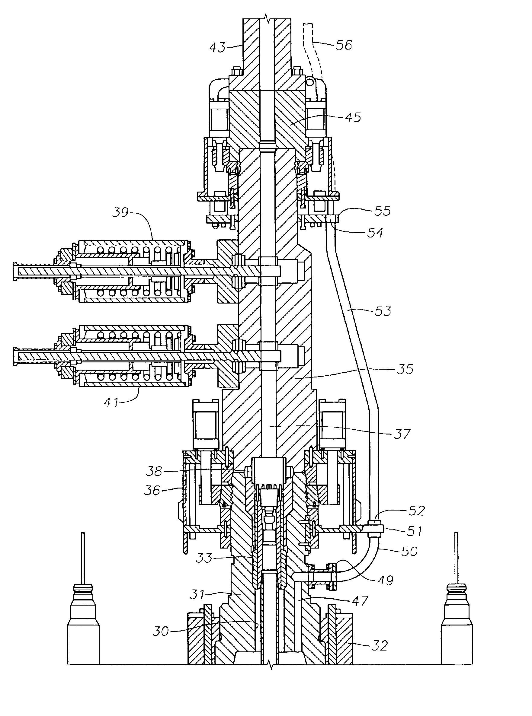
[0021]A string of production tubing 27 extends through the smallest diameter casing 21. The well will produce fluids through tubing 27. A production tubing annulus or tubing annulus 29 exists between tubing 27 and the production casing or smallest diameter casing 21. It is important to monitor the tubing annulus 29 for leakage and also to be able...


PUM


Abstract

A subsea wellhead assembly allows communication between a production tubing annulus and a conduit in fluid communication with a platform above. The wellhead assembly has a tubing hanger that is held relative to a tubular wellhead member of a subsea well by a tubing hanger support. A string of tubing extends from the tubing hanger into the well, defining an annulus around the tubing. The conduit communicates with the tubing annulus through a tubing annulus passage. The tubing annulus passage has a portion extending through the tubing hanger support. The wellhead member supports a valve block located between the tubing hanger support and the riser. The tubing annulus passage has another portion that registers with the portion of the passage in the tubing hanger support. The conduit stabs into valve block portion of the tubing annulus passage when the riser connects to the upper end of the valve block.

Description

RELATED APPLICATIONS[0001]Applicant claims priority for the invention described herein through a United States provisional patent application titled “Tubing Annulus Communication for Vertical Flow Subsea Well,” having U.S. patent application Ser. No. 60 / 357,230, which was filed on Feb. 15, 2002, and which is incorporated herein by reference in its entirety.BACKGROUND OF INVENTION[0002]1. Field of the Invention[0003]This invention relates in general to subsea well production, and in particular to a subsea well that has vertical production passages and tubing annulus communication other than through the tubing hanger.[0004]2. Background of the Invention[0005]A subsea well that is capable of producing oil or gas will have an outer or low pressure wellhead housing secured to a string of conductor pipe that extends some short depth into the well. An inner or high pressure wellhead housing lands in the outer wellhead housing. The tubular wellhead member is secured to an outer string of ca...

Claims


Application Information

Patent Timeline
Patent Type & Authority Patents(United States)
IPC IPC(8): E21B33/064E21B33/03E21B33/035E21B33/043
CPCE21B33/0355E21B33/064E21B33/043
Inventor RADI, AMINCAPESIUS, MICHAEL E.ELLIS, FIFE B.VOSS, ROBERT K.
Owner VETCO GRAY
Why Eureka
Try Eureka