
Apparatus for taking up slack of wire harness

a technology apparatus, which is applied in the direction of coupling device connection, cable arrangement between relatively moving parts, instruments, etc., can solve the problems of wire harness vibration, difficult to compact the apparatus for taking up slack, and abnormal noise during the traveling of the automobil

Inactive Publication Date: 2002-11-19
YAZAKI CORP
View PDF15 Cites 3 Cited by
  • Summary
  • Abstract
  • Description
  • Claims
  • Application Information

AI Technical Summary

Problems solved by technology

On the other hand, in a case where the door is closed, unless the wire harness is taken up on the vehicle body side, the wire harness remains in the slackened state at the opening / closing position, so that there are possibilities that the wire harness can become disconnected due to being pinched between the door and the vehicle body, or the sheath portion exfoliates, resulting in short-circuit.
However, since the wire -harness is not protected at its drawn-out portion, and since the aforementioned sheath portion is likely to undergo peeling or the like, and a slack is formed in the accommodating box, there has been a problem in that abnormal noise can occur during the traveling of the automobile.
However, the above-described expanding and contracting structure for a circuit member for a door has the following problem.
Namely, to accommodate the protector, the housing for accommodating the aforementioned expanding and contracting structure, i.e., the housing making up the apparatus for taking up the slack, becomes equal to or greater in length than the expanding and contacting stroke of the wire harness, so that there is a problem in that it is difficult to make compact the apparatus for taking up the slack.
In addition, since the positioning is effected by making use of the resiliency of the wire harness itself, if vibrations are applied to the wire harness in conjunction with the traveling of the automobile, for example, there are cases where the wire harness vibrates and the abnormal noise occurs.
Furthermore, there has been a problem in that the structure is complex and the number of component parts is large, leading to higher cost.
Further, since the connecting terminals are provided at an end portion of the wire harness led out from the first opening, and the connector housing in which the connecting terminals are fixed in the terminal accommodating chamber is molded integrally on the outer side of the housing, it is unnecessary to provide a fixing member for the wire harness, in the vicinity of the first opening, and a member for attaching the connector for connection to the wire harness is also unnecessary.

Method used


Image

  • Apparatus for taking up slack of wire harness
  • Apparatus for taking up slack of wire harness
  • Apparatus for taking up slack of wire harness

Examples


first embodiment

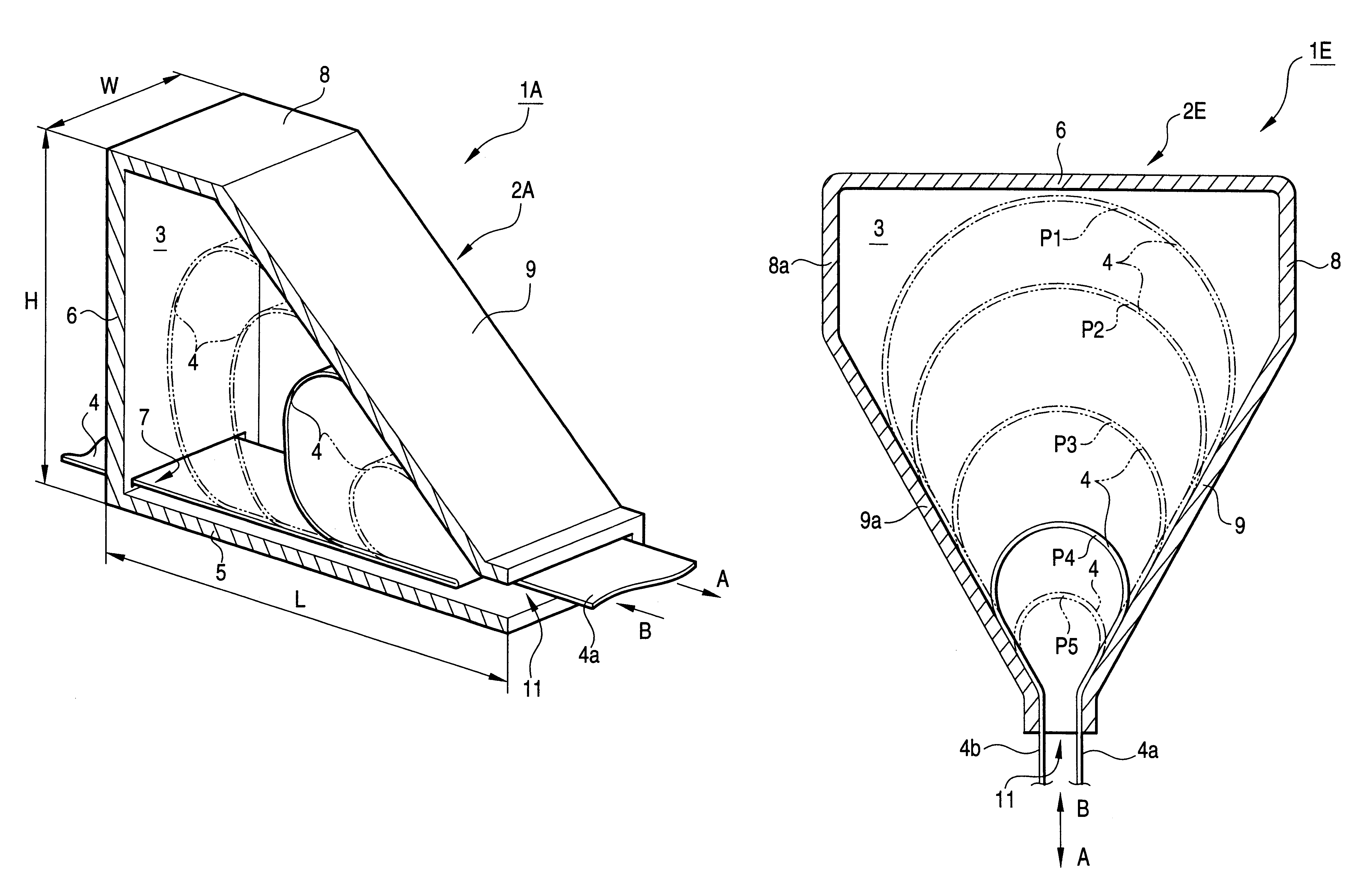
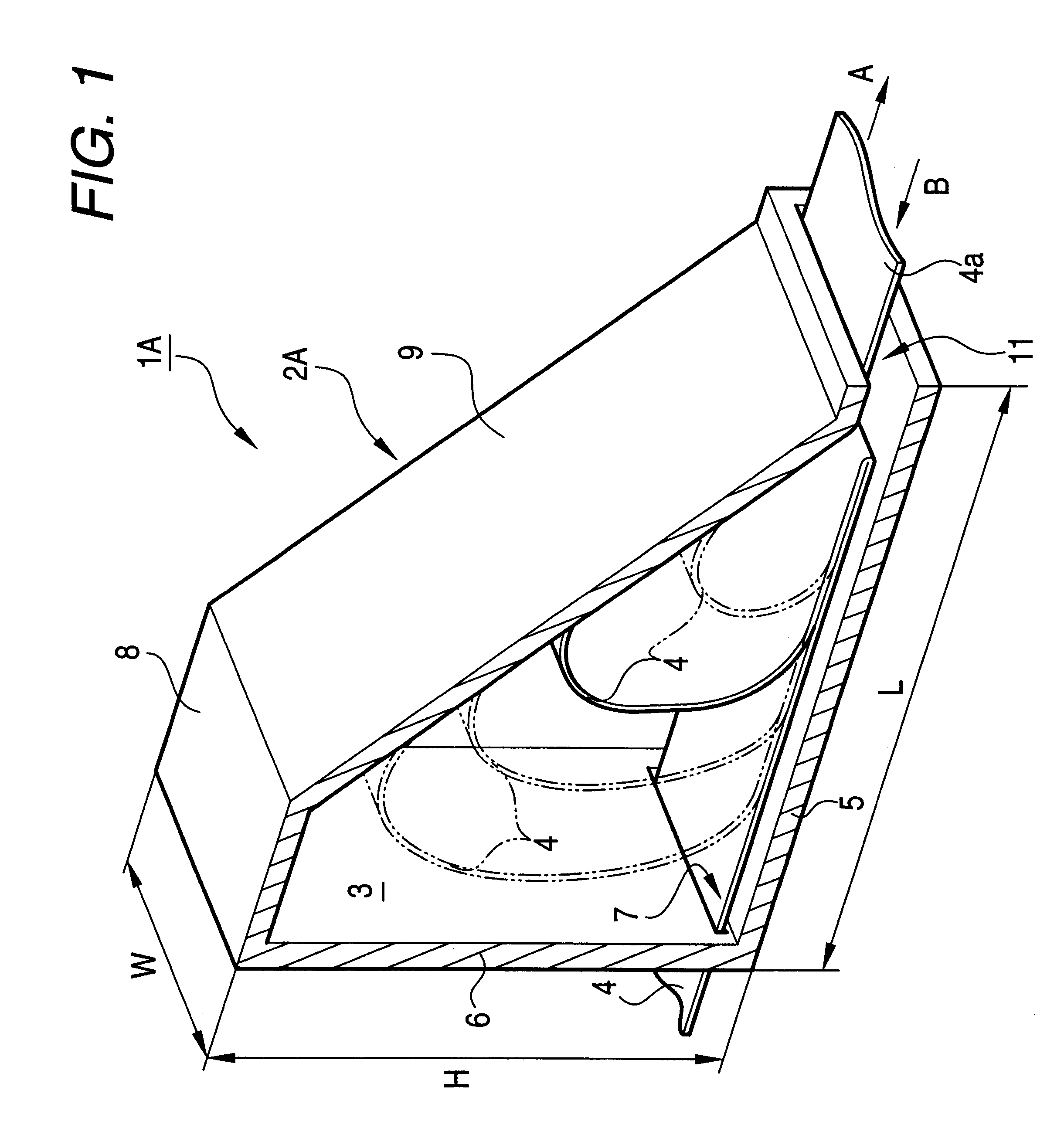
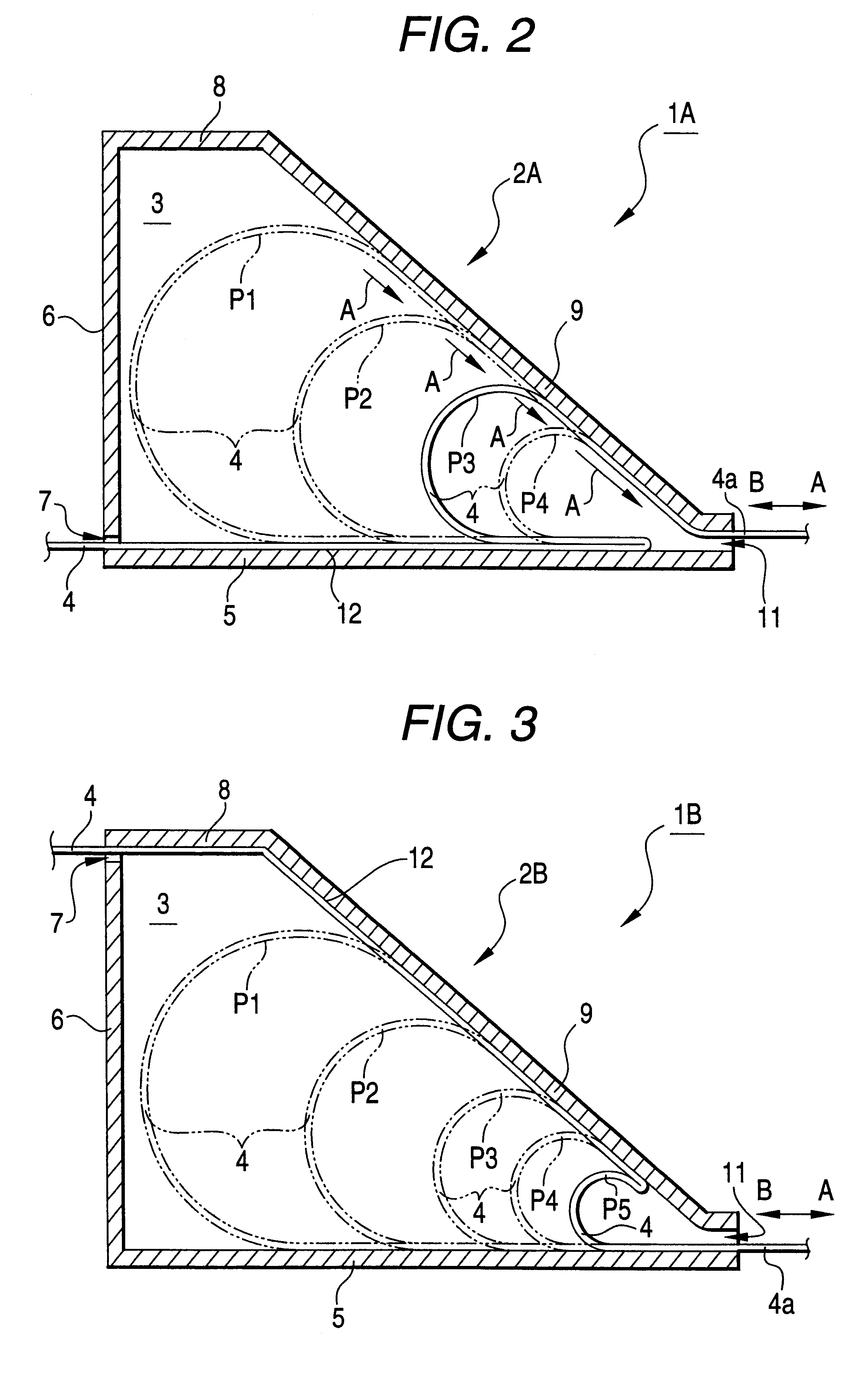
Referring now to FIGS. 1 and 2, a detailed description will be given of a first embodiment of an apparatus for taking up the slack of a wire harness in accordance with the invention. FIG. 1 is a perspective view illustrating the construction and operation of the apparatus for taking up the slack of a wire harness in accordance with this embodiment, and FIG. 2 is a cross-sectional view illustrating the drawing out (extension) of the wire harness and the slack taking-up operation.

An apparatus 1A for taking up the slack of a wire harness (hereinafter simply abbreviated as the slack taking-up apparatus) shown in FIGS. 1 and 2 comprises a housing 2A whose vertical cross-sectional shape formed in a substantially trapezoidal shape, and a flexible flat wire harness (hereinafter simply abbreviated as the wire harness) 4 which is accommodated in a bent state in a wire-harness accommodating space 3 in the housing 2A and is drawn out of the housing 2A.

The housing 2A has a first side plate 5 ser...

second embodiment

Next, referring to FIG. 3, a detailed description will be given of a second embodiment of the apparatus for taking up the slack of a wire harness in accordance with the invention. FIG. 3 is a cross-sectional view illustrating the drawing out (extension) of the wire harness and the slack taking-up operation. It should be noted that since the major difference between this embodiment and the above-described first embodiment lies in that the position where the wire harness 4 is introduced into a housing 2B as well as its bonded position are changed, the members which function in the same way as described above will be denoted by the same reference numerals, and a description thereof will be omitted.

In an apparatus 1B for taking up the slack of a wire harness in this embodiment, the first opening 7 is formed at the upper end of the vertical side plate 6, and the wire harness 4 introduced from the first opening 7 is installed up to a vicinity of the second opening 11 along the top plate 8...

third embodiment

Next, referring to FIG. 4, a detailed description will be given of a third embodiment of the apparatus for taking up the slack of a wire harness in accordance with the invention. FIG. 4 is a cross-sectional view illustrating the drawing out (extension) of the wire harness and the slack taking-up operation. It should be noted that the major difference between this embodiment and the above-described embodiments lies in that the introduction of the wire harness 4 into a housing 2C and the leading of the wire harness 4 out of it are effected through the single opening 11. Accordingly, those members that function in the same way as described above will be denoted by the same reference numerals, and a description thereof will be omitted.

In an apparatus 1C for taking up the slack of a wire harness in this embodiment, although the first side plate 5, the vertical side plate 6, the top plate 8, and the second side plate 9 are arranged in the same way as those of the foregoing embodiments, th...


PUM


Abstract

An apparatus (1A) for taking up the slack of a wire harness takes up the slack of a flexible, flat wire harness (4) which is accommodated in a housing (2A) having a second side plate (9) formed in an inclined manner with respect to a first side plate (5), and which is drawn out of the housing (2A). This second side plate (9) is provided in such a manner as to assume a gradual downward gradient from a first opening (7) side toward a second opening (11) side. The wire harness (4) which is inserted through the first opening (7) is partially bonded to the first side plate (5), is once folded back toward the introducing side, i.e., the first opening (7) side, in a state in which the curvature of bending is practically nil. The wire harness (4) is then turned back toward the second opening (11) side in a state of being curved arcuately by the resilient action of the wire harness (4) itself, and is drawn out of the housing (2A) through the second opening (11).

Description

1. Technical Field of the InventionThe present invention relates to an apparatus for taking up the slack of a wire harness which is drawn out when the door of an automobile, for example, is opened for preventing the occurrence of the slack between the door and the vehicle body when the door is closed.2. Related ArtAmong vehicles such as automobiles, there is a type in which lights and switches are provided on a rear window or door side, and the lights and switches are connected to a control apparatus provided on the vehicle body side by a wire harness or the like. Therefore, if, for example, the door is opened, the wire harness is drawn out from the vehicle body side in accordance with the angle of its opening.On the other hand, in a case where the door is closed, unless the wire harness is taken up on the vehicle body side, the wire harness remains in the slackened state at the opening / closing position, so that there are possibilities that the wire harness can become disconnected d...

Claims


Application Information

Patent Timeline
Patent Type & Authority Patents(United States)
IPC IPC(8): B60R16/02H02G11/00H01R13/72H01R13/00H01R35/02H01R35/00
CPCB60R16/0215H01R13/72H02G11/00H01R12/68H01R35/025
Inventor TSUKAMOTO, MASASHI
Owner YAZAKI CORP
Learn More