Safety brake arrangement in a brake actuator

a safety brake and actuator technology, applied in the direction of brake arrangement with braking member, brake cylinder, braking system, etc., can solve the problems of not being able to apply spring brake at all, and the solution of normal spring brake is not the right on

Inactive Publication Date: 2002-12-10
SAB WABCO SA
View PDF8 Cites 17 Cited by
  • Summary
  • Abstract
  • Description
  • Claims
  • Application Information

AI Technical Summary

Benefits of technology

A brake actuator of the kind defined above, fulfilling all requirements and specifications, is according to the invention attained in that the actuator also comprises a safety brake arrangement including at least one powerful spring, acting in the brake application

Problems solved by technology

In certain cases, however, a normal spring brake is not the right solution.
Especially if the

Method used


Image

  • Safety brake arrangement in a brake actuator
  • Safety brake arrangement in a brake actuator
  • Safety brake arrangement in a brake actuator

Examples


Embodiment Construction

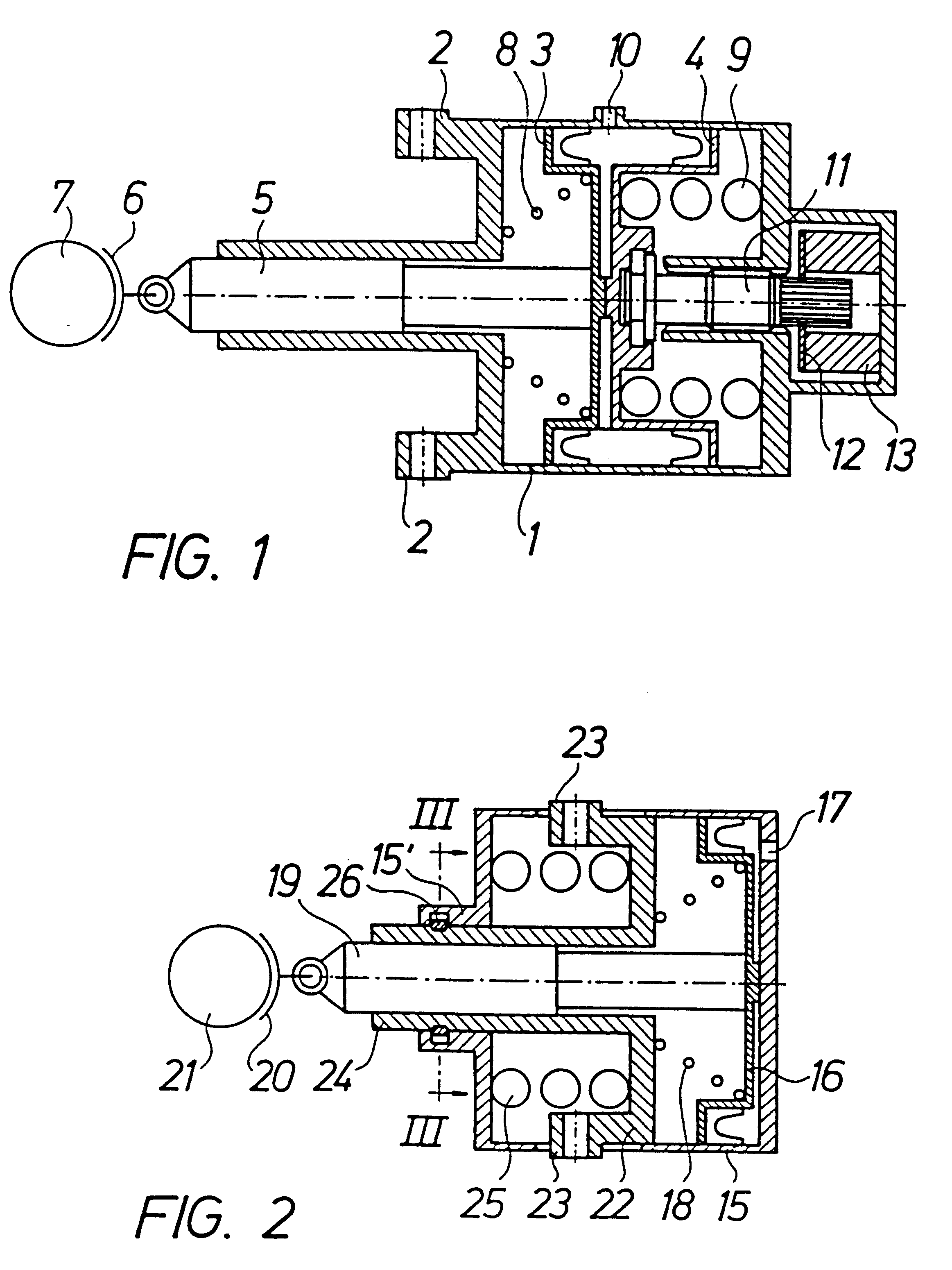
In a simple version a block brake actuator according to the invention may be of the design shown in FIG. 1.

In a common cylinder 1, which is provided with attachments 2 for its mounting for example to the under-frame of a vehicle, two sealed pistons 3 and 4 are axially movable. The first piston 3 is a service piston connected to a push rod 5, preferably comprising a mechanical slack adjuster of any type, and further to a brake block 6 for braking engagement with a wheel 7 to be braked. A return spring 8 for the service piston 3 is arranged in the cylinder 1.

The second piston 4 is a spring brake or safety brake piston, which is acted on in the brake application direction by a powerful safety brake spring 9 of compression type. An inlet 10 for pressurized air is arranged on the cylinder 1 between the two pistons 3 and 4, which accordingly are pressed apart at the admission of air under such pressure that the force of the safety brake spring 9 is overcome.

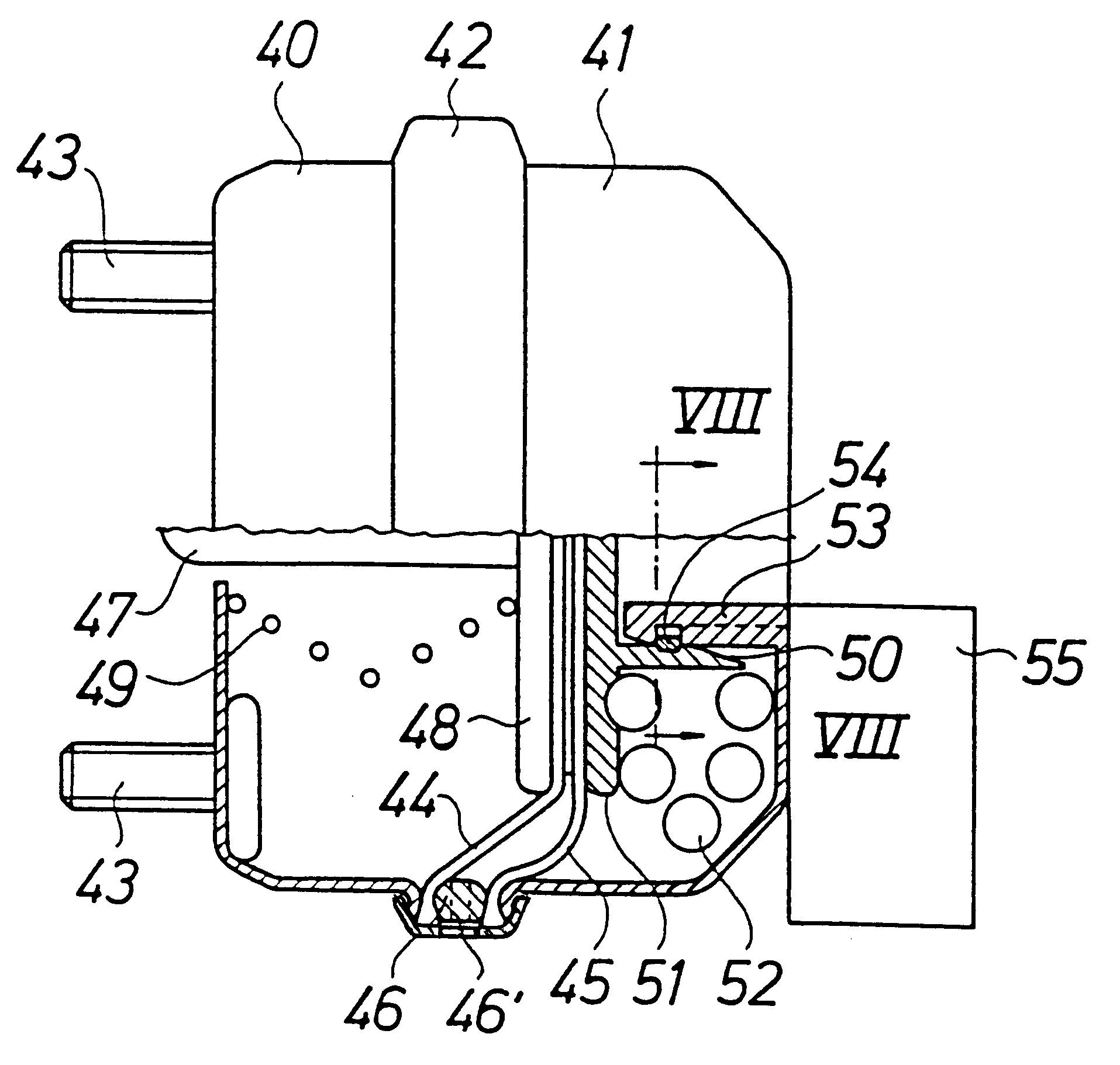
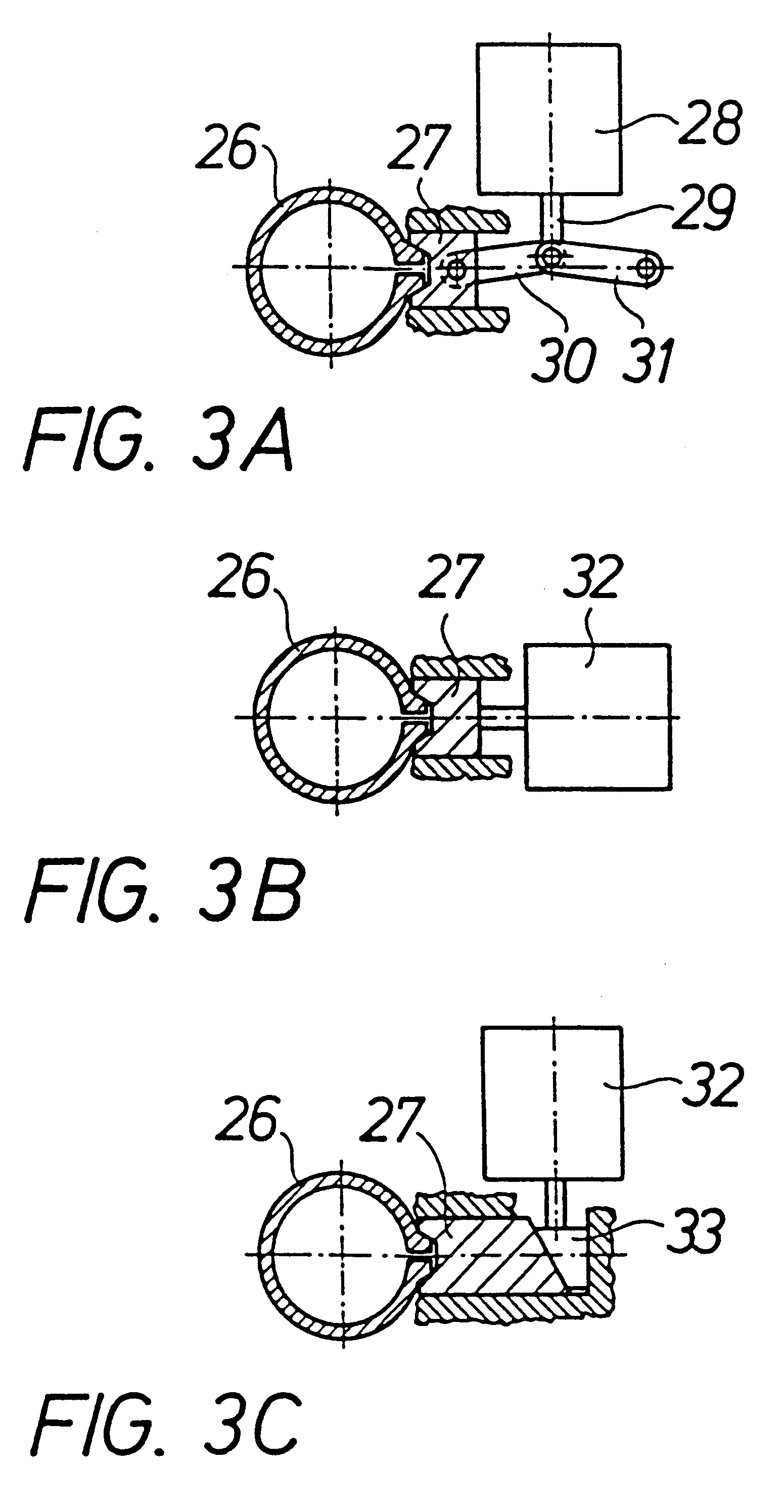
Means are provided for releasab...


PUM


Abstract

A brake actuator for delivering a brake force through a brake block or br pad to a wheel or disc to be braked comprises in a housing (1) a service brake arrangement (3, 5). The actuator also comprises a safety brake arrangement (4, 9) including at least one powerful spring (9), acting in the brake application direction, means for tensioning the spring by the reaction force at a service brake application, and mechanical means (11, 12, 13) for locking the spring to the housing in a tension state. These locking means can be released at will for accomplishing a safety brake application.

Description

This invention relates to a brake actuator for delivering a brake force through a brake block or brake pad to a wheel or disc to be braked, the actuator comprising in a housing a service brake arrangement.TECHNICAL BACKGROUNDBrake actuators for service braking of vehicles, both rail vehicles and automotive vehicles, are well known. Such actuators are normally pneumatically or hydraulically operated, but also electro-mechanical actuators are known. Service braking of a vehicle may occur as block braking or disc braking, as is well known in the art.It is in many cases desirable that the vehicle is braked if the supply of the normal brake medium, normally the pneumatic or hydraulic pressure, fails. The normal way of achieving this is by means of a so called spring brake, in which a powerful compression spring is held compressed and inactive by means of pneumatic or hydraulic pressure in a separate chamber; if this pressure drops for any reason the spring will expand and accomplish spri...

Claims


Application Information

Patent Timeline
IPC IPC(8): B61H1/00B60T17/00B60T17/08B60T13/02F01B9/00
CPCB60T17/083B61H1/003F16D2127/008
Inventor SEVERINSSON, LARS
Owner SAB WABCO SA
Why Eureka
Try Eureka