Removable structures for mounting computer drive devices, pivotable between operating and service positions

a drive device and computer technology, applied in the direction of electrical apparatus construction details, electrical apparatus casings/cabinets/drawers, instruments, etc., can solve the problem of not providing access to insert screws

Inactive Publication Date: 2003-01-14
LENOVO PC INT
View PDF7 Cites 38 Cited by
  • Summary
  • Abstract
  • Description
  • Claims
  • Application Information

AI Technical Summary

Problems solved by technology

Often, these bays do not provide access to insert screws to enga

Method used


Image

  • Removable structures for mounting computer drive devices, pivotable between operating and service positions
  • Removable structures for mounting computer drive devices, pivotable between operating and service positions
  • Removable structures for mounting computer drive devices, pivotable between operating and service positions

Examples


Embodiment Construction

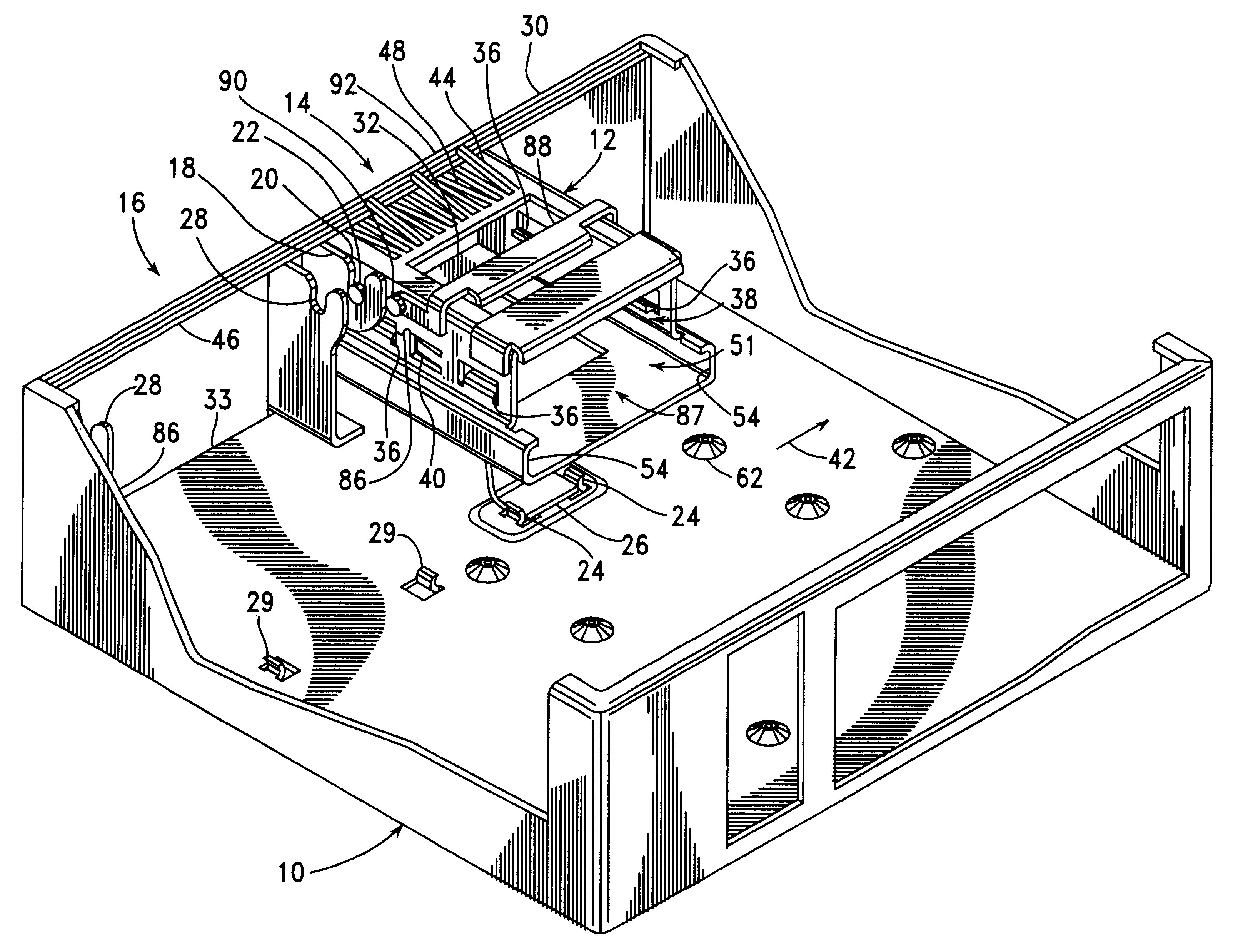
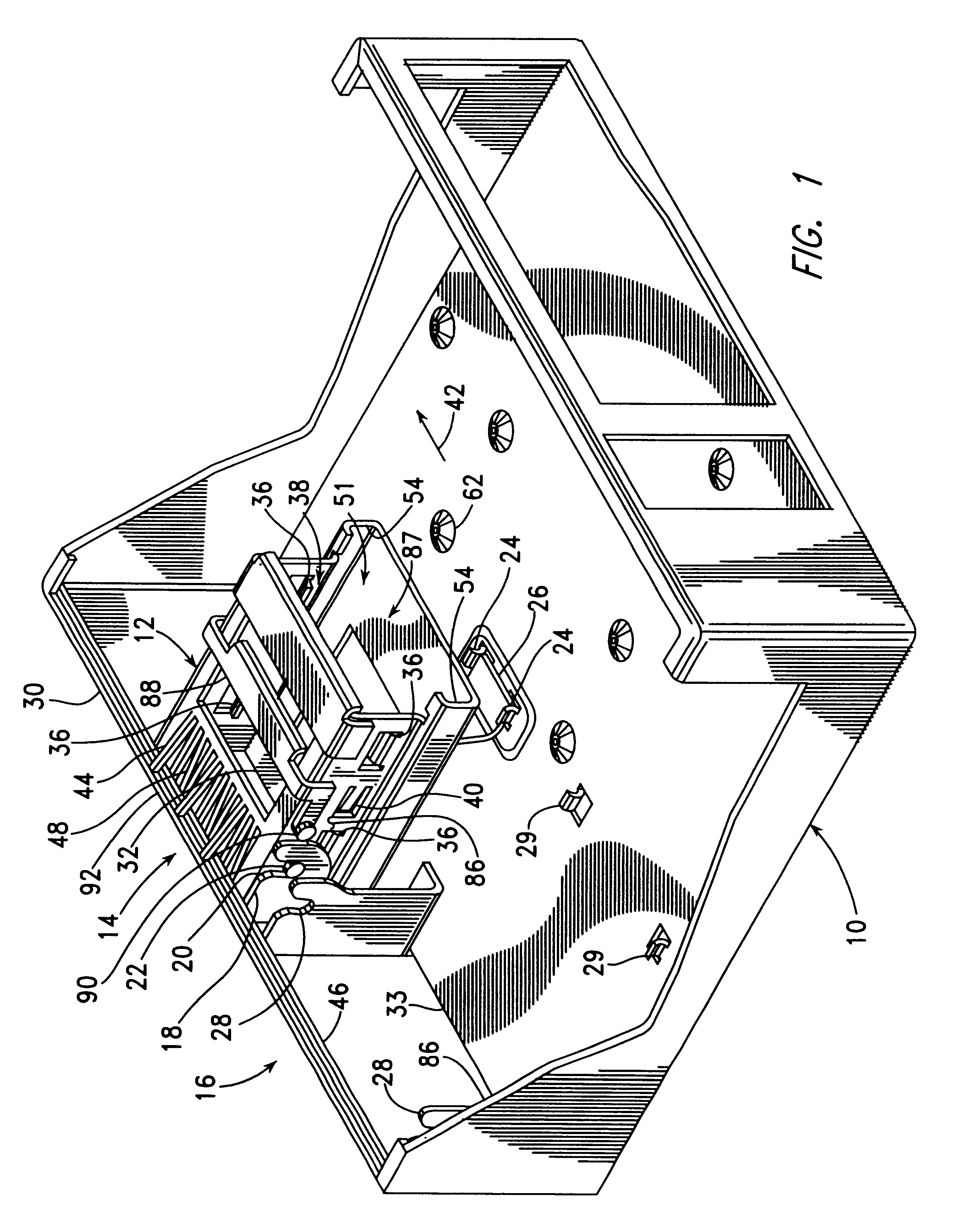
FIG. 1 is an isometric view of a computer system frame 10 including a rotatable and removable drive mounting structure 12, which are together built in accordance with the present invention. The drive mounting structure 12 is shown in the lower, or operating position, which is used during system operation. The frame 10 includes a first drive mounting area 14, in which the first drive mounting structure 12 is provided for mounting 3.5-inch drive units, and a second drive mounting area 16, in which a second drive mounting structure (not shown) is provided for mounting 5.25-inch drive units.

The drive mounting areas 14, 16 of the frame 10 include a number of features associated with the mounting of the first drive mounting structure 12 and of the second drive mounting structure (not shown). For example, the first drive mounting area 14 includes a first pivotal mounting structure in the form of a pair of slotted brackets 18, formed as integral portions of the frame 10, with slots 20 remov...


PUM


Abstract

A computing system includes a frame and a drive mounting structure for mounting one or more drive units within the computing system, with the drive mounting structure being pivotally and removably mounted on the frame to move between an operating position, in which an internal end of a drive unit mounted within the drive mounting structure is held within the computing system, and a service position, in which the internal end of the drive unit extends outward from the computing system. In the service position, access is provided to an open end of the drive mounting structure, into which the drive unit can be installed, to the internal end of the drive unit, for attachment of a cable, and to a side of the drive mounting structure, through which fasteners are driven to mount the drive unit within the drive mounting structure.

Description

BACKGROUND INFORMATION1. Field of InventionThis invention relates to a cage or bracket for mounting a drive device within a computer, and, more particularly, to a cage or bracket movable into a position providing access to screws mounting the drive device and easily removable from the computer.2. Description of the Related ArtTypical computer systems include a number of device bays, in which drive devices are mounted by installation from the front of the system. Such drive devices, which are often called DASD (Direct Access Storage Device) drives, include floppy disk drives, hard disk drives, and CD ROM drives. Often, these bays do not provide access to insert screws to engage the threaded mounting holes provided within the drive devices. While these mounting holes are typically provided along the left and right sides of the drive device, and often also along the bottom surface of the drive device, in many computing systems the bays only provide for attachment access from the front ...

Claims


Application Information

Patent Timeline
IPC IPC(8): G06F1/18
CPCG06F1/187G06F1/184
Inventor BARINA, RICHARD MICHAELBASS, TIMOTHY S.HERRING, DEAN FREDERICKOTTO, WILLIAM FREDSAMPER, RODRIGOWISE, SUSAN POHL
Owner LENOVO PC INT
Why Eureka
Try Eureka